
Gas inlet volute and combustion gas turbine

A volute and turbine technology, applied to gas turbine devices, mechanical equipment, engine components, etc., can solve problems such as separation of blade pressure surfaces, affecting turbine work, and blockage of flow passages

Inactive Publication Date: 2018-02-23
新奥能源动力科技(上海)有限公司
View PDF0 Cites 0 Cited by
  • Summary
  • Abstract
  • Description
  • Claims
  • Application Information

AI Technical Summary

Problems solved by technology

[0003] At present, the gas turbine adopts an axial flow turbine, and the intake volute needs to introduce the air flow from the combustion chamber through a pipe perpendicular to the centerline of the unit, and the gradual shrinkage of the cross-sectional area of ​​the pipe through the volute distributes the air flow evenly in the circumferential direction , and then turn 90° to turn into a circular axial flow to the blade of the high-pressure guide inlet of the gas turbine. In order to ensure the efficiency of the turbine, the airflow angle (the angle between the airflow direction and the axial direction) of the high-pressure guide inlet usually needs to be as far as possible. It may be close to 0°, but because the outlet of the inlet volute has a relatively large circumferential velocity, the airflow angle at the outlet of the inlet volute is usually relatively large, and in order to ensure the efficiency of the turbine, the turbine inlet airflow angle is designed to be axial When the air is inhaled, the turbine inlet will have a negative angle of attack, which will cause serious separation of the pressure surface of the blade, block the flow channel, and affect the work of the turbine.
However, it is feasible to reduce the peripheral speed by enlarging the volume of the volute, thereby reducing the airflow angle at the outlet of the volute, but it will significantly increase the volume of the whole machine.

Method used


Image

  • Gas inlet volute and combustion gas turbine
  • Gas inlet volute and combustion gas turbine
  • Gas inlet volute and combustion gas turbine

Examples


Embodiment Construction

[0025] The following will clearly and completely describe the technical solutions in the embodiments of the present invention with reference to the accompanying drawings in the embodiments of the present invention. Obviously, the described embodiments are only some of the embodiments of the present invention, not all of them. Based on the embodiments of the present invention, all other embodiments obtained by persons of ordinary skill in the art without making creative efforts belong to the protection scope of the present invention.

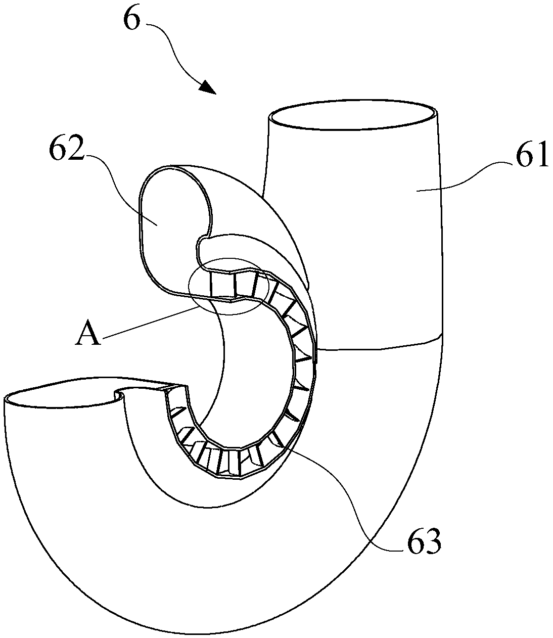
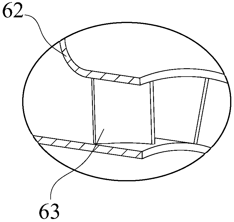
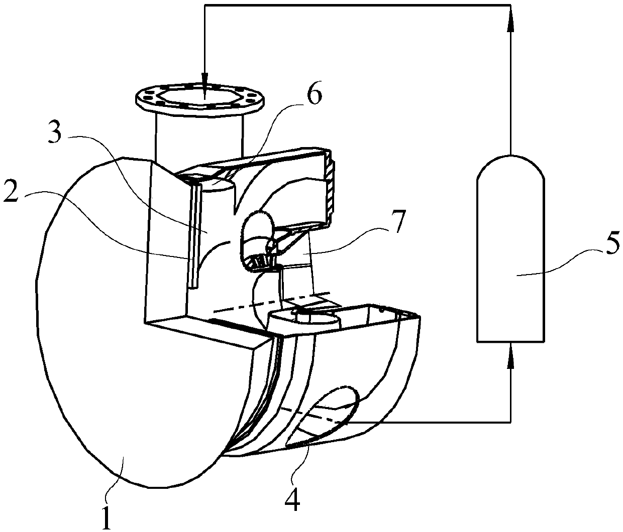
[0026] Such as figure 1 , figure 2 as well as image 3 As shown, an intake volute 6 is used to connect the combustion chamber 5 and the high-pressure guide 7, including a contraction tube 61, an annular tube 62 and at least one set of guide vanes 63, wherein:

[0027] The shrink tube 61 is connected to the gas outlet of the combustion chamber 5, and along the direction away from the combustion chamber 5, the cross-sectional area of ​​the shrin...


PUM


Abstract

The invention relates to the field of energy system design and discloses a gas inlet volute and a combustion gas turbine. The gas inlet volute is used for connecting a combustion chamber and a high-pressure guide and comprises a shrinkage tube, an annular tube and at least one group of guide blades, wherein the shrinkage tube is connected with the gas outlet of the combustion chamber; in a direction opposite to the combustion chamber, the area of the cross section of the shrinkage tube is gradually reduced; the annular tube is communicated with the gas outlet of the shrinkage tube and the high-pressure guide; the gas flow direction of the annular tube is perpendicular to that of the shrinkage tube; at least one group of the guide blades are uniformly arranged inside the annular tube in thecircumferential direction of the annular tube to form a gas guide channel; when passing through the gas guide channel, a high-temperature high-pressure combustion gas is deviated to a direction approximate to the axial direction from a relatively large outlet gas flow angle under the action of the guide blades, then a relatively small inlet gas flow angle of the high-pressure guide is formed, thepower action and the efficiency that a turbine is pushed by the high-temperature high-pressure combustion gas are ensured, a relatively small gas flow angle of a gas fed into the guide-pressure guideis formed, and in addition, the gas inlet volute is compact in structure and convenient to manufacture.

Description

technical field [0001] The invention relates to the field of energy system design, in particular to an intake volute and a gas turbine. Background technique [0002] In the field of energy technology, a gas turbine is a rotary power machine that uses continuously flowing gas as a working medium to convert heat energy into mechanical energy. It is mainly composed of a compressor, a combustion chamber and a gas turbine. The cross-sectional shape and area between the tube combustion chamber and the high-pressure guide of the gas turbine are generally connected by the intake volute. The intake volute is a gas collection chamber with a shape similar to a snail shell. Introduce and collect gas. [0003] At present, the gas turbine adopts an axial flow turbine, and the intake volute needs to introduce the air flow from the combustion chamber through a pipe perpendicular to the centerline of the unit, and the gradual shrinkage of the cross-sectional area of ​​the pipe through the v...

Claims


Application Information

Patent Timeline
IPC IPC(8): F02C7/057F01D25/24F01D9/04
CPCF01D9/041F01D25/24F02C7/057F02C7/04
Inventor 刘正王利民李成勤宋俊波潘豪王威威韩孟克
Owner 新奥能源动力科技(上海)有限公司
Learn More