Heat treatment quenching device
A technology of quenching device and condensing box, which is applied in the direction of quenching device, heat treatment equipment, manufacturing tools, etc., can solve the problems of adding water and water resources, and achieve the effect of avoiding waste and facilitating quenching treatment.
Inactive Publication Date: 2018-02-23
马鞍山祥源机械厂
View PDF7 Cites 0 Cited by
- Summary
- Abstract
- Description
- Claims
- Application Information
AI Technical Summary
Problems solved by technology
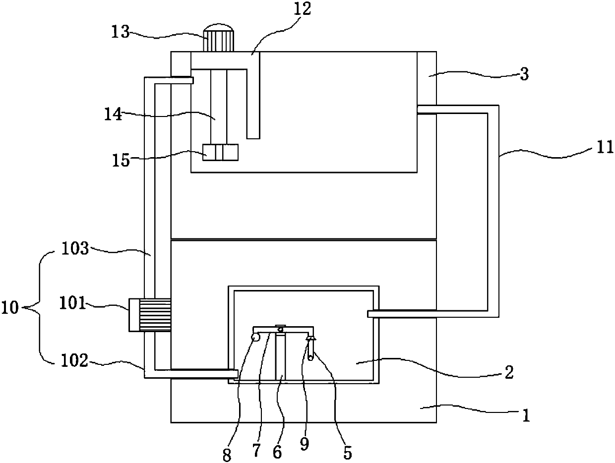
[0005] The purpose of the present invention is to solve the problem of water resource waste caused by the inability of condensed water to circulate and the need to continuously add water to the condensing tank, and proposes a heat treatment quenching device
Method used
View moreImage
Smart ImageViewing Examples
Examples
Embodiment Construction
[0017] The following will clearly and completely describe the technical solutions in the embodiments of the present invention with reference to the accompanying drawings in the embodiments of the present invention. Obviously, the described embodiments are only some, not all, embodiments of the present invention.
Login to View More PUM
 Abstract
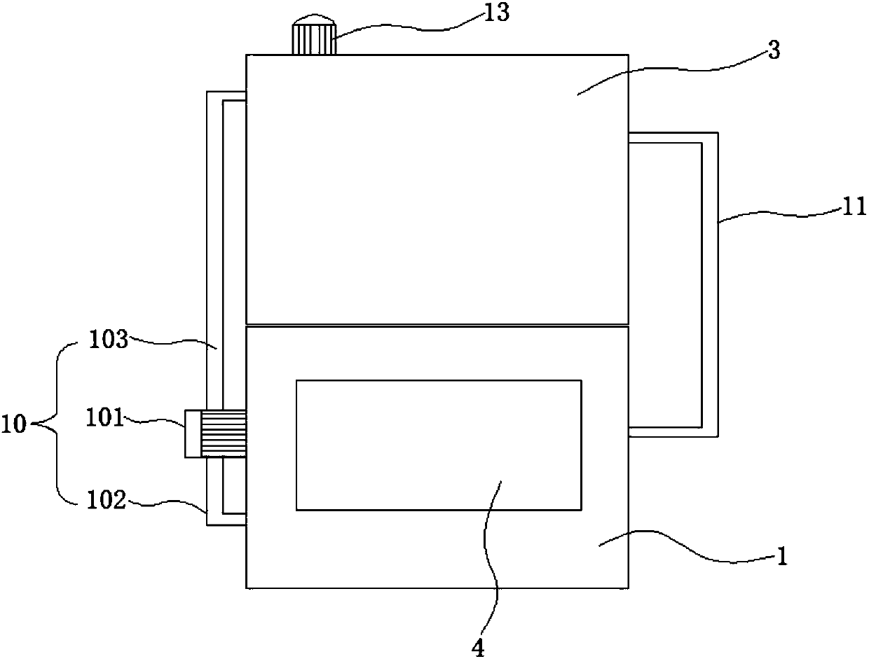
The invention discloses a quenching device for heat treatment, which comprises a condensation box, a water accumulation chamber is arranged inside the condensation box, a cooling tank is arranged on the top of the condensation box, and a water discharge tank is fixedly connected to the outer side wall of the condensation box. The outlet end of the water tank is provided with a first water pipe, and the end of the first water pipe away from the water tank runs through the condensation tank and extends to the water accumulation chamber. The bottom of the water accumulation chamber is fixedly connected with a support rod, and the support rod rotates A control rod is connected, and one end of the control rod is fixedly connected with a floating ball. In the present invention, through the cooperation of the water inlet mechanism and the second water pipe, the cooling water in the cooling tank is continuously circulated, so as to avoid the waste of water resources. In addition, through the cooperation of the floating ball, the control rod, the sealing plug and the first water pipe, the accumulation of water is ensured. The water chamber always contains condensed water, thereby ensuring the continuous battery life of the condensed water in the cooling tank, so that people can continue to perform quenching treatment.
Description
technical field [0001] The invention relates to the technical field of production and processing equipment, in particular to a heat treatment quenching device. Background technique [0002] With the development of science and technology, we have more and more demand for copper, iron, etc., because it is convenient for people to process them into various machines and necessities in our life, because of its high hardness and wide distribution, it is quickly popular among people. of favor. [0003] Copper and iron raw materials mainly need to be synthesized, and the synthesis process needs to be carried out by calcination, so as to facilitate processing into the shape of the product that people need, and the quenching device is mainly for annealing to reduce the temperature of the product, but the current quenching device is through The condensing box cools the water, and then puts the product in the cooling tank and cools it through the condensed water. However, the condensed...
Claims
Login to View More Application Information
Patent Timeline
 Patent Type & Authority Applications(China)
IPC IPC(8): C21D1/64
CPCC21D1/64
Inventor 查德祥
Owner 马鞍山祥源机械厂
- R&D Engineer
- R&D Manager
- IP Professional
- Industry Leading Data Capabilities
- Powerful AI technology
- Patent DNA Extraction
Learn More Browse by: Latest US Patents, China's latest patents, Technical Efficacy Thesaurus, Application Domain, Technology Topic, Popular Technical Reports.
© 2024 PatSnap. All rights reserved.Legal|Privacy policy|Modern Slavery Act Transparency Statement|Sitemap|About US| Contact US: help@patsnap.com


