
Lift claw for annular workpiece

A ring-shaped workpiece and hanging claw technology, which is applied in the field of automatic conveying equipment, can solve the problems of complex hanging claw structure, high manufacturing cost, hidden safety hazards, etc., and achieve the effects of convenient use, low production cost, and improved production efficiency.

Inactive Publication Date: 2018-02-23
黄石佳鼎自动化科技有限公司
View PDF0 Cites 3 Cited by
  • Summary
  • Abstract
  • Description
  • Claims
  • Application Information

AI Technical Summary

Problems solved by technology

However, the existing claw structure is relatively complex, the manufacturing cost is high, and due to too many movable joints, it is inconvenient to use and often slips, causing damage to the workpiece, and there are serious safety hazards

Method used


Image

  • Lift claw for annular workpiece
  • Lift claw for annular workpiece
  • Lift claw for annular workpiece

Examples


Embodiment Construction

[0016] The present invention is described in further detail now in conjunction with accompanying drawing. These drawings are all simplified schematic diagrams, which only illustrate the basic structure of the present invention in a schematic manner, so they only show the configurations related to the present invention.

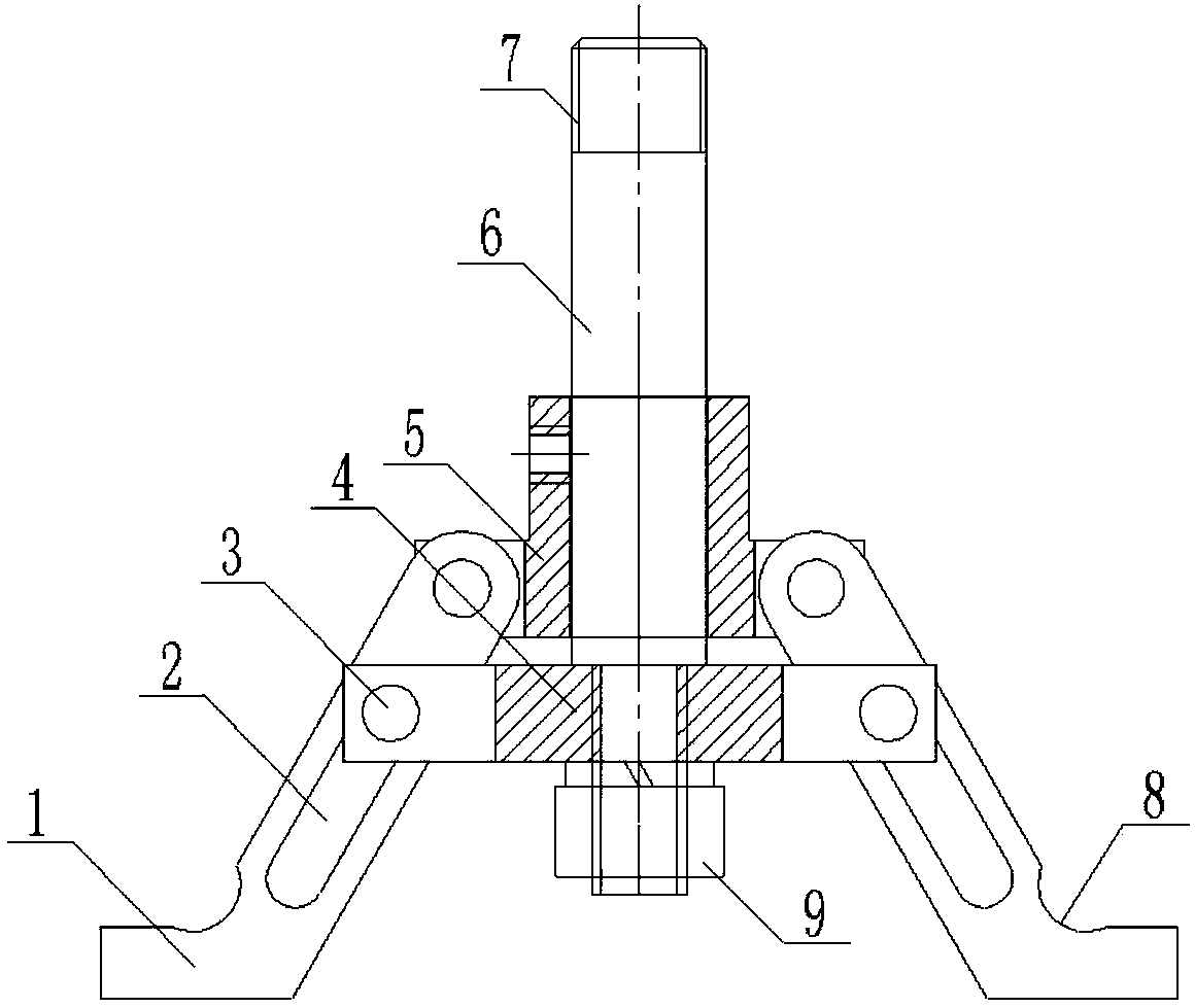
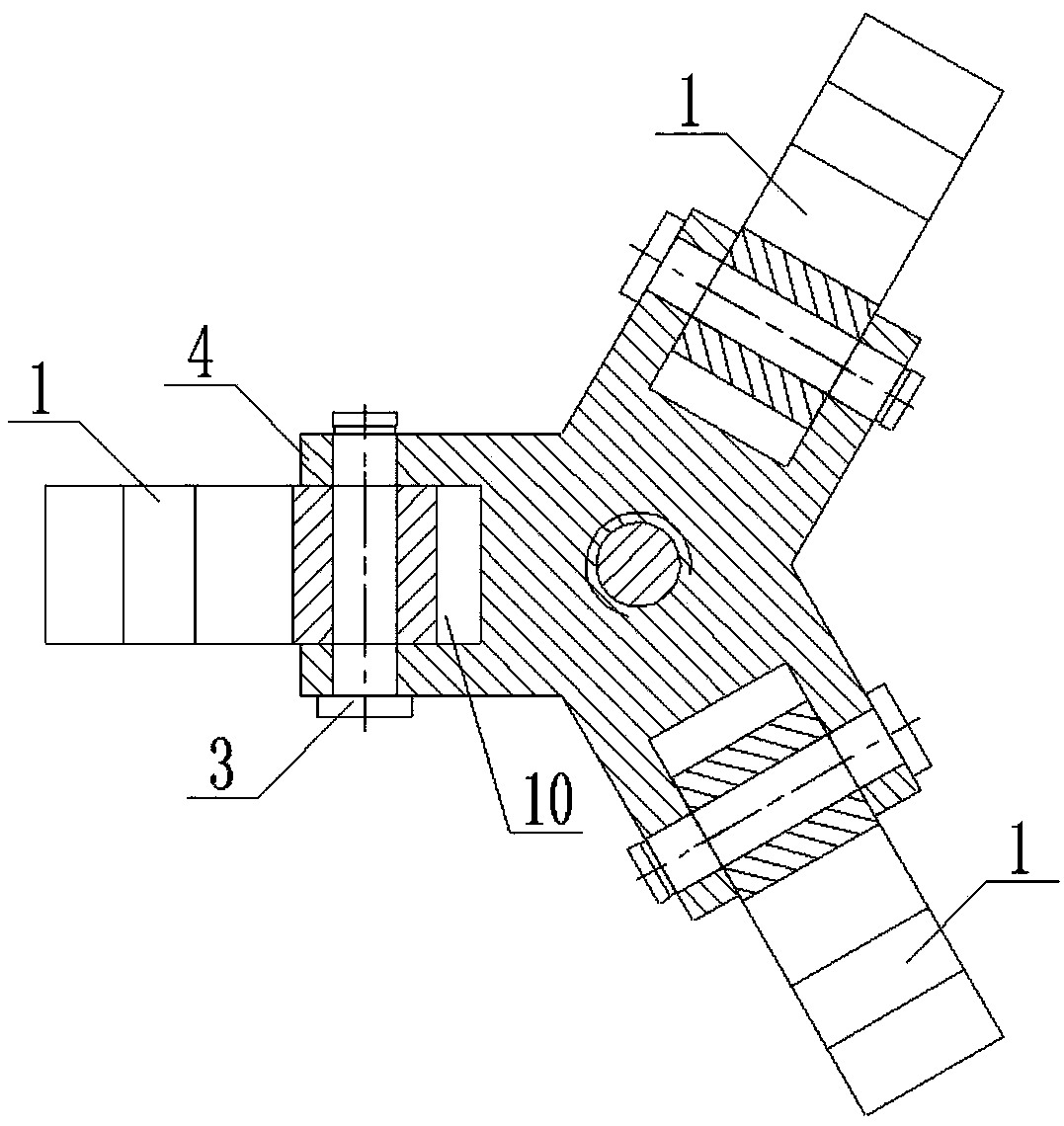
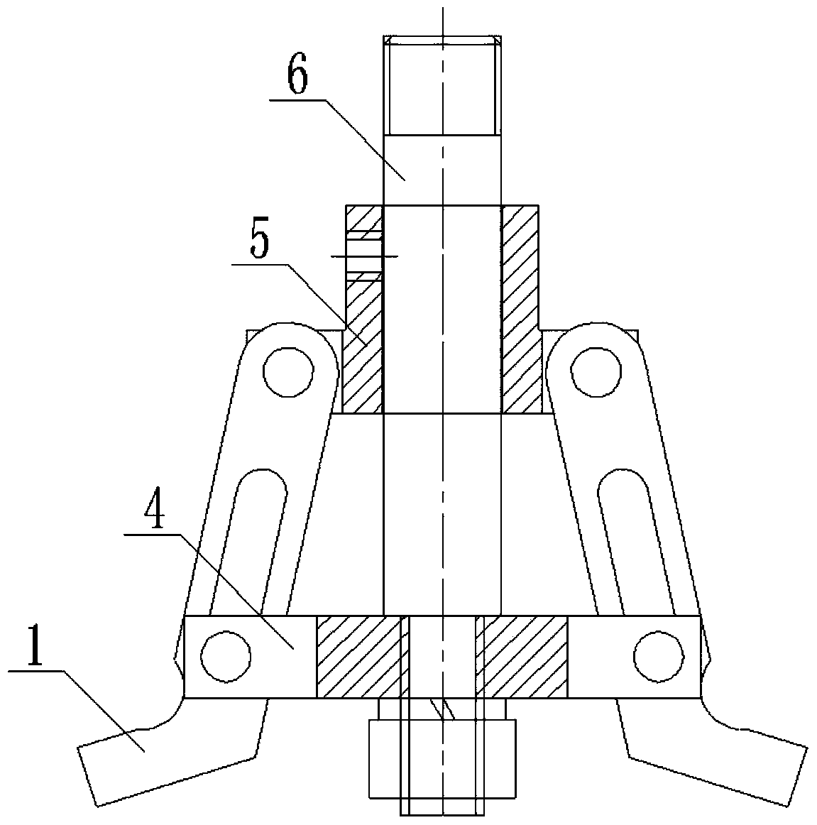
[0017] Figure 1 to Figure 4 A hanging claw for a circular workpiece shown includes a hook support 5, a limit slider 4 located below the hook support 5, and sequentially penetrates through the hook support 5, a limit slide The pull rod 6 in the center of the block 4, the outer circumference of the lower end of the hook support 5 is hinged with a hook 1, the middle part of the hook 1 is provided with a chute 2, and a pin shaft 3 runs through the chute 2, The outer circumference of the limit slider 4 is provided with a bayonet 10, the hook 1 is snapped into the bayonet 10 through the pin 3, and the lower end of the pull rod 6 is fixed on the limit slide. Cente...


PUM


Abstract

The present invention relates to the technical field of automatic conveying equipment, in particular to a lifting claw for ring-shaped workpieces, which includes a hook support, a limit slider located under the hook support, and sequentially penetrates through the hook support. seat, the pull rod in the center of the limit slider, the outer circumference of the lower end of the hook support is hinged with a hook, the middle part of the hook is provided with a chute, and a pin shaft runs through the chute, and the limit A bayonet is provided on the outer circumference of the positioning slider, the hook is snapped into the bayonet through the pin shaft, and the lower end of the pull rod is fixed at the center of the limiting slider. The invention has simple structure, low production cost, convenient and reliable use, and improves production efficiency and use safety.

Description

technical field [0001] The invention relates to the technical field of automatic conveying equipment, in particular to a lifting claw for ring-shaped workpieces. Background technique [0002] In automatic conveying equipment, the use of lifting claws is extremely frequent, which effectively replaces manual handling, improves production efficiency, and reduces labor intensity. Especially for some large workpieces, which cannot be carried by manpower, and there are potential safety hazards, the use of lifting claws has solved this problem better. However, the existing lifting claw structure is relatively complicated, the manufacturing cost is high, and due to too many movable joints, it is inconvenient to use, and often slips, causing damage to the workpiece, and there are serious safety hazards. Contents of the invention [0003] The object of the present invention is to solve the problems existing in the above-mentioned background technology, and to provide a lifting claw...

Claims


Application Information

Patent Timeline
Patent Type & Authority Applications(China)
IPC IPC(8): B66C1/22
CPCB66C1/22
Inventor 汪建家
Owner 黄石佳鼎自动化科技有限公司
Learn More