A splicing solar refrigeration device

A solar refrigeration and splicing technology, which is applied in transportation and packaging, heating/cooling equipment, supporting structures of photovoltaic modules, etc., and can solve problems such as damage to refrigerators

Active Publication Date: 2020-06-30
林秀平
View PDF6 Cites 0 Cited by
  • Summary
  • Abstract
  • Description
  • Claims
  • Application Information

AI Technical Summary

Problems solved by technology

[0003] The patent application number is 201310085281.0 discloses a solar ventilation and refrigeration device, including a housing, a refrigerator, a cover plate and a solar panel, and the refrigerator is located in the housing; the cover plate is composed of a cover plate cover and a cover plate seat , the cover seat is located in the housing and distributed at both ends of the refrigerator, the cover seat is provided with an air channel; the cover cover is provided with an air inlet and an exhaust port; the One side of the bottom plate of the casing is provided with a lifting mechanism, and the lifting mechanism is fixedly connected with the solar cell panel through the air inlet and the exhaust port. The lifting function is realized under the action of the mechanism; relying on the surrounding solar resources, the solar panel is used to provide electric energy to the refrigerator and the lifting mechanism of the solar ventilation and refrigeration device, so as to realize the continuous supply of cold air to the interior of the vehicle exposed to the sun, effectively It solves the problem of excessive temperature rise in the car when parking in the open air, and improves the comfort of the vehicle. However, the device cannot easily and conveniently detect and maintain the refrigerator when it is in use. At the same time, the refrigerator is exposed outside when it is not in use. Damage to the refrigerator

Method used


Image

  • A splicing solar refrigeration device
  • A splicing solar refrigeration device
  • A splicing solar refrigeration device

Examples


Embodiment

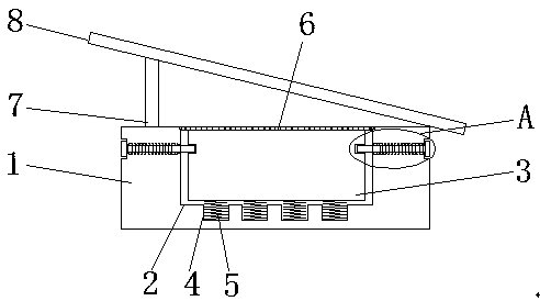
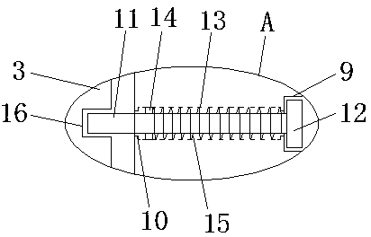
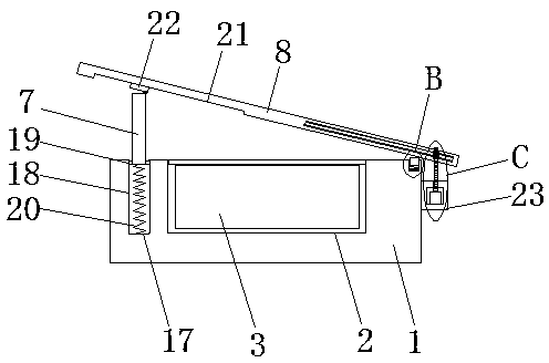
[0024] Example: refer to Figure 1-6 , a spliced ​​solar refrigeration device, comprising a housing 1, a placement slot 2 is provided on the top side of the housing 1, a refrigerator 3 is placed in the placement slot 2, positioning slots 16 are provided on both sides of the refrigerator 3, and the housing 1 There are installation grooves 9 on both sides, and a through hole 10 is opened on the inner wall of the installation groove 9 away from the opening, and the through hole 10 is connected with the placement groove 2, and a positioning rod 11 is slidably installed in the through hole 10, and the positioning Both ends of the rod 11 extend to the outside of the through hole 10, one end of the positioning rod 11 located in the mounting groove 9 is fixedly installed with a mounting block 12, and the end of the positioning rod 11 away from the mounting block 12 extends into the placement groove 2, and is aligned with the positioning groove. 16, a plurality of first grooves 4 are a...


PUM


Abstract

The invention discloses a spliced type solar refrigerating device. The device includes a shell, a placement groove is formed in the top side of the shell, a refrigerating machine is placed in the placement groove, the two sides of the refrigerating machine are provided with positioning grooves, the two sides of the shell are both provided with installation grooves, the inner wall of one side, awayfrom an opening, of each installation groove is provided with a through hole, the through holes are communicated with the placement groove, the through holes are internally provided with positioningrods in a sliding mode, the two ends of each positioning rod extend to the outside of the corresponding through hole, the ends, located in installation grooves, of the positioning rods are fixedly provided with installation blocks, the ends, away from the installation blocks, of the positioning rods extend in the placement grooves, the positioning rods are matched with the positioning grooves, anda solar panel is obliquely arranged above the shell. The device can facilitate the stable installation and dismantling of the refrigerating machine, meanwhile, the angle position of the solar panel can be conveniently adjusted, the refrigerating machine is sealed through the solar panel, and damage caused when the refrigerating machine is not used is prevented.

Description

technical field [0001] The invention relates to the technical field of refrigeration devices, in particular to a spliced ​​solar refrigeration device. Background technique [0002] In the process of parking vehicles in the open air in summer, due to the strong sunlight, the heat inside the car cannot be dissipated in time, which makes the temperature inside the car rise too high, which reduces the comfort of people when riding. There are two ways to solve this problem: one, keep ventilation in the car; two, feed cold air into the car. This just needs to install exhaust fan in the car, or keep the air conditioner in the car to work, both of these methods require electric energy, and the battery in the car can't work for a long time when it is parked, so it can't be realized. Considering that the excessive temperature rise when the vehicle is parked in the open air is usually caused by strong sunlight, and solar cells are a mature technology, 1 square meter of direct sunlight...

Claims


Application Information

Patent Timeline
Patent Type & Authority Patents(China)
IPC IPC(8): B60H1/32H02S20/30
CPCB60H1/32H02S20/30Y02E10/50
Inventor 魏爱玲
Owner 林秀平
Why Eureka
Try Eureka