
Cement feeding device

A cement and air suction device technology, which is applied in the direction of selling raw material supply devices, etc., can solve the problems of dust flying, harsh environment on the construction site, and large pollution, and achieve the effect of reducing dust

Inactive Publication Date: 2018-02-23
陆玉山
View PDF0 Cites 2 Cited by
  • Summary
  • Abstract
  • Description
  • Claims
  • Application Information

AI Technical Summary

Problems solved by technology

[0002] Concrete is often used on the construction site. Concrete is obtained by mixing cement, sand and gravel with a mixer. However, the existing concrete batching process is polluted and dusty, which makes the environment on the construction site worse. bad hair

Method used


Image

  • Cement feeding device

Examples


Embodiment Construction

[0011] The present invention will be further described below in conjunction with the embodiments and with reference to the accompanying drawings. It should be understood that the following specific embodiments are only used to illustrate the present invention and are not intended to limit the scope of the present invention. It should be noted that the words "front", "rear", "left", "right", "upper" and "lower" used in the following description refer to the direction in the figure, and the words "inner" and "outer ” refer to directions towards or away from the geometric center of a particular part, respectively.

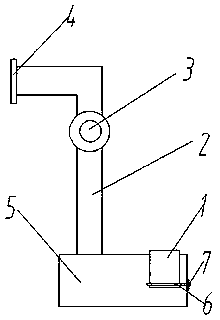
[0012] Such as figure 1 Described a kind of cement feeding device, described cement feeding device comprises cement placing box 5, pipeline 2 and suction device 3, one end of described pipeline 3 is connected with cement placing box 5, and the other end is connected with connecting The flange 4 is provided with a suction device 3 on the pipeline 2; and a discharge po...


PUM


Abstract

The invention discloses a cement feeding device. The cement feeding device includes a cement placement box, a pipeline and a suction device. One end of the pipeline is connected with the cement placement box, and the other end is connected with a connecting flange. The pipeline is provided with a suction device; the cement storage box is also provided with a discharge port. A cement feeding device provided by the present invention can reduce dust by setting a cement storage box and attracting the cement into the mixing tank through a suction device. The amount of cement placed.

Description

technical field [0001] The invention relates to a feeding device, in particular to a cement feeding device. Background technique [0002] Concrete is often used on the construction site. Concrete is obtained by mixing cement, sand and gravel with a mixer. However, the existing concrete batching process is polluted and dusty, which makes the environment on the construction site worse. Bad hair. Contents of the invention [0003] The object of the present invention is to provide a cement feeding device in order to overcome the above problems. [0004] In order to achieve the above object, the method adopted in the present invention is: a cement feeding device, the cement feeding device includes a cement placement box, a pipeline and a suction device, one end of the pipeline is connected with the cement placement box, and the other One end is connected with a connecting flange, and a suction device is arranged on the pipeline; a discharge port is also arranged on the cement...

Claims


Application Information

Patent Timeline
IPC IPC(8): B28C7/06
CPCB28C7/062
Inventor 陆玉山
Owner 陆玉山
Learn More