Defoaming liquid storage tank used for vinegar filling process

A liquid storage tank and process technology, which is applied in the direction of liquid degassing, foam dispersion/prevention, and liquid degassing through filtration, etc. It can solve the problems of easy fouling of the stirring device, low work efficiency, and increased cost, and achieve defoaming efficiency High, easy to clean, improve the effect of fluidity

Inactive Publication Date: 2018-02-23
四川谋席科技有限公司
View PDF1 Cites 1 Cited by
  • Summary
  • Abstract
  • Description
  • Claims
  • Application Information

AI Technical Summary

Problems solved by technology

[0005] 1. For the filling of vinegar, the method of stirring is used to eliminate air bubbles. There is a problem that the stirring device in the liquid storage tank is easy to scale, and the stirring device is frequently replaced, resulting in an increase in cost;
[0006] 2. In the process of vinegar filling process, a single stirring method is used to eliminate the bubbles in the liquid, which has the problem of low work efficiency

Method used


Image

  • Defoaming liquid storage tank used for vinegar filling process
  • Defoaming liquid storage tank used for vinegar filling process
  • Defoaming liquid storage tank used for vinegar filling process

Examples


Embodiment 1

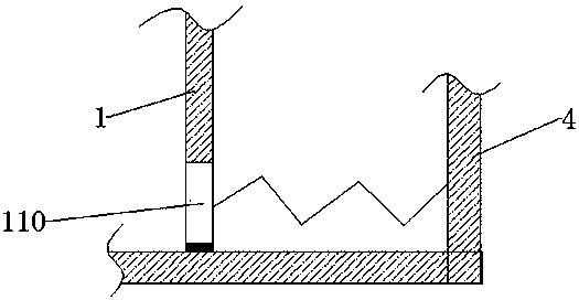
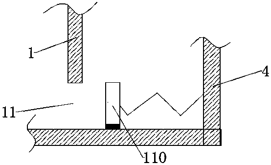
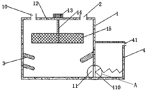
[0025] Such as figure 1 , shown in 2, a kind of defoaming liquid storage tank that is used for vinegar filling process, comprises tank body 1, the feed inlet 10 that is arranged on the tank body 1 top; Also includes the gas outlet 2 that is arranged on the tank body 1 top, The air outlet 2 is connected with a vacuum pump. Before filling, the liquid storage tank is exhausted, so that there is no air in the liquid storage tank during filling, so as to prevent the air from convecting the liquid when it flows in; the inner side of the tank body 1 Several heating plates 3 are arranged on the wall, and the heating plates 3 heat the liquid in the tank body 1, accelerate the flow velocity of the liquid molecules, reduce the stability of the bubbles, and achieve the purpose of eliminating the bubbles; the bottom end of the side wall of the tank body 1 is provided with a first Discharge port 11, the first discharge port 11 is provided with a spring retainer 110, and a layer of rubber is...

Embodiment 2

[0028] On the basis of the defoaming liquid storage tank used in the vinegar filling process described in Example 1, it is further optimized, and the heating plate 3 is detachably connected to the side wall. Because vinegar is easy to scale, the heating plate 3 is set to be detachable, and the heating plate 3 can be cleaned in time to increase the effective service life of the heating plate 3.

Embodiment 3

[0030] Further optimized on the basis of a defoaming liquid storage tank used in the vinegar filling process described in Example 1, the tank body 1 includes a tank cover 12, and the tank cover 12 is screwed to the side wall of the tank body 1 . The tank cover 12 can be disassembled, which is convenient for cleaning the inside of the tank body 1 and prevents the vinegar from polluting the device.


PUM


Abstract

The invention discloses a defoaming liquid storage tank used for the vinegar filling process, which comprises a tank body and a feed inlet arranged on the top of the tank body; and an air outlet arranged on the top of the tank body, and the air outlet is connected with a vacuum pump; There are several heating plates on the inner wall of the tank body; the bottom end of the side wall of the tank body is provided with a first discharge port, and a spring stopper is provided on the first discharge port, and a spring stopper is laid on the side contacting the bottom of the tank body. A layer of rubber, the first discharge port is connected with a second liquid storage tank, the height of the second liquid storage tank is lower than that of the tank body, and the top of the side wall of the second liquid storage tank is provided with a second discharge port. The second liquid storage tank set in the present invention is lower than the height of the tank body. Because the height of the liquid in the tank is different, the hydraulic pressure is different, so that the bubbles rise in the liquid, and the principle of the U-shaped tube is used to make the liquid flow with few bubbles at the bottom of the tank body. Enter the second liquid storage tank to ensure that the liquid flowing out of the liquid storage tank does not contain air bubbles, so as to achieve the purpose of accurate filling and measurement.

Description

technical field [0001] The invention relates to the filling field, in particular to a liquid storage tank with a defoaming function. Background technique [0002] The filling machine is widely used in medicine, food, daily chemical, pesticide and other industries, and can fill various liquids. At present, when filling vinegar, stirring and heating are often used to eliminate air bubbles, so as to ensure the accuracy of filling measurement. [0003] The defoaming device before filling high-viscosity beverages (application number 201320604305.4), including a tank body, is characterized in that: a transmission motor is arranged on the top of the tank body, and a stirring paddle is arranged inside the tank body, and the transmission motor passes through the stirring shaft and The top of the tank is also provided with a feed pipe and a gas outlet pipe, one end of the gas outlet pipe is provided with a check valve, the other end of the gas outlet pipe is provided with a vacuum pu...

Claims


Application Information

Patent Timeline
Patent Type & Authority Applications(China)
IPC IPC(8): B01D19/02
CPCB01D19/0031B01D19/0073B01D19/02
Inventor 邹远龙
Owner 四川谋席科技有限公司
Why Eureka
Try Eureka