
Solder resisting plug hole air guiding plate and manufacturing method therefor

A technology of air guide plate and plug hole, which is applied in the direction of manufacturing tools, printed circuit manufacturing, electrical components, etc., can solve the problems of high production cost of air guide plate and increase of overall operating cost, etc., achieve good support effect, and simple and fast processing method , Ease of use

Inactive Publication Date: 2018-02-16
SHANTOU LUCKY STAR PCB CO LTD
View PDF10 Cites 1 Cited by
  • Summary
  • Abstract
  • Description
  • Claims
  • Application Information

AI Technical Summary

Problems solved by technology

[0002] In response to the continuous rise in the price of sheet metal, the production cost of the air guide plate used for the solder plug hole is simultaneously high (sheet material, drilling costs) and the production process is time-consuming, and the company’s overall operating cost is simultaneously increasing. Therefore, in order to optimize the air guide plate In order to reduce costs and improve efficiency, it is necessary to develop an economical, applicable, and reusable air guide plate

Method used


Image

  • Solder resisting plug hole air guiding plate and manufacturing method therefor

Examples


Embodiment Construction

[0018] Preferred embodiments of the present invention will be described in detail below.

[0019] The base plate is made of epoxy resin glass fiber board with Rockwell hardness ≥ 115. The base plate is dotted with blind gongs in a matrix, and the flat-topped cone columns that match the air guide requirements of printed board printing are formed as residues to obtain the air guide plate.

[0020] The preparation of the substrate, according to the thickness and hardness requirements, is designed to use multiple 7628 series prepregs of epoxy glass fiber and release film, which are pressed under high temperature and high pressure under vacuum conditions. It is characterized in that an overall substrate with an overall thickness of 3.0-3.2 mm, high uniformity and high hardness is obtained.

[0021] After cutting the overall substrate to a size of 620mm in length and 530mm in width, the step of setting the depth of blind gongs on the substrate includes the air guiding fulcrum with a...


PUM

PropertyMeasurementUnit
Thicknessaaaaaaaaaa
Diameteraaaaaaaaaa
Depthaaaaaaaaaa

Abstract

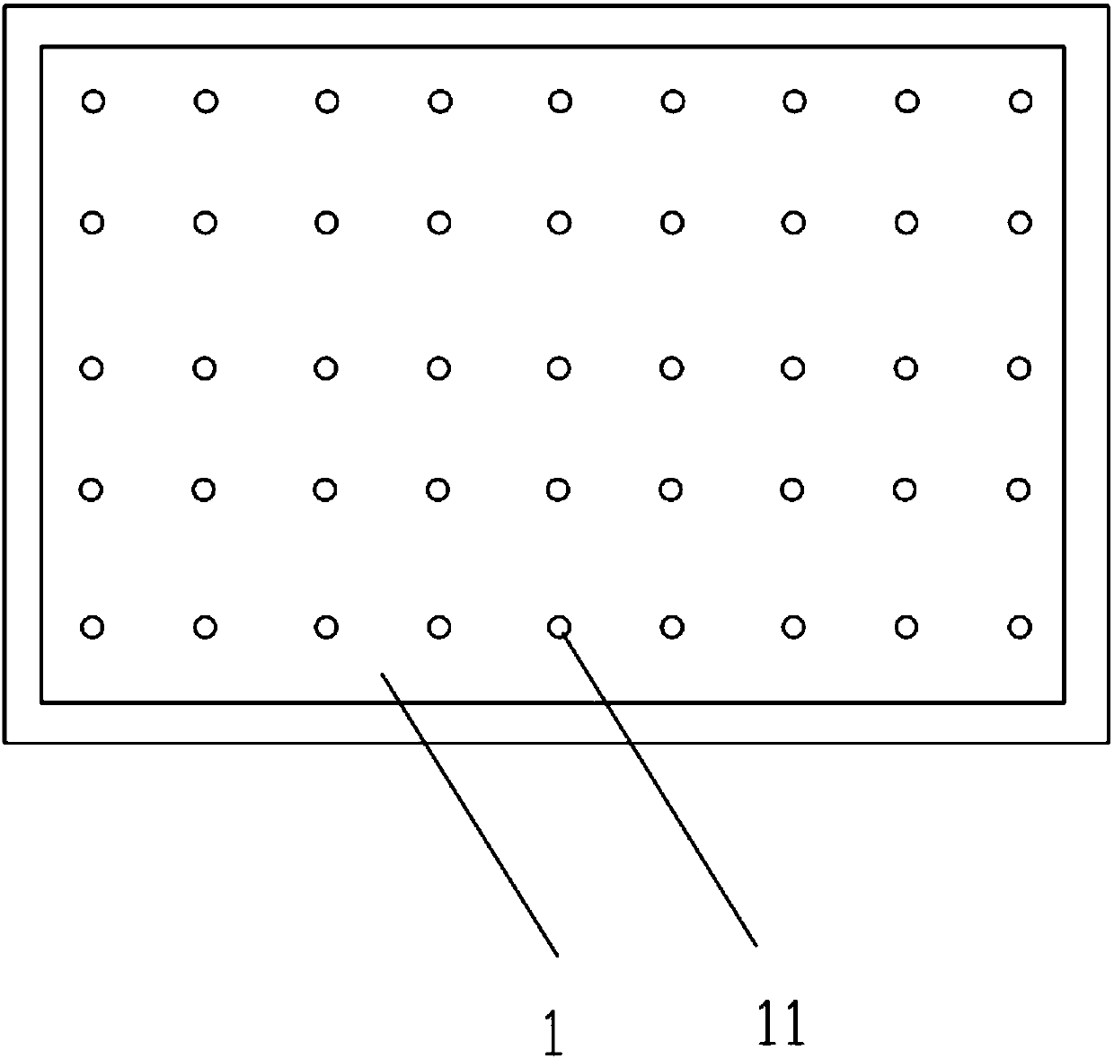
The invention belongs to a production auxiliary tool of an electronic product, and specifically relates to a solder resisting plug hole air guiding plate and a manufacturing method therefor. A plurality of flat conical columns are arranged on the surface of a substrate; and the distances between the flat conical columns are equal. The manufacturing method comprises the following steps of 1) adopting an epoxy resin glass fiber plate with Rockwell hardness of greater than or equal to 115 to manufacture the substrate, performing blind cutting on the substrate based on matrix points, and forming the flat conical columns which can satisfy printing and air guiding requirements of a printed circuit board from the residual part so as to obtain an air guiding plate; 2) enabling multiple pieces of epoxy glass fiber prepregs of the substrate to be matched with a release film, and performing high-temperature and high-pressure lamination in a vacuum condition; 3) after the whole substrate is cut, performing blind cutting on the substrate at fixed depth, and forming rectangular air guiding supporting points through blind cutting; and 4) processing the cylinder which is already formed through blind cutting into the flat cones with a small top and a large bottom. The processing method is simple and efficient and high in rate of finished products; the air guiding plate is very convenient to use, and the plate can be well supported; and the air guiding plate is formed in the mode of selecting the blind cutting supporting point.

Description

technical field [0001] The invention belongs to a production auxiliary tool for electronic products, in particular to a solder-resisting plug hole air guide plate and a manufacturing method thereof. Background technique [0002] In view of the continuous rise in the price of sheet metal, the production cost of the air guide plate used for the solder plug hole is simultaneously high (sheet material, drilling cost) and the production process is time-consuming, and the company’s overall operating cost is simultaneously increasing. Therefore, in order to optimize the air guide plate In order to reduce costs and improve efficiency, it is necessary to develop an economical, applicable, and reusable air guide plate. Contents of the invention [0003] Aiming at the above defects of the prior art, the present invention provides a solder-resisting plug hole gas guide plate with convenient and simple operation, stable quality of processed products, and low cost. [0004] A solder-re...

Claims


Application Information

Patent Timeline
IPC IPC(8): H05K3/00B23C3/00
CPCB23C3/00H05K3/0094
Inventor 李健伟余同德周俊黎少明林云生
Owner SHANTOU LUCKY STAR PCB CO LTD
Learn More