
Wireless charging device

A technology of wireless charging and placing boards, which is applied in the direction of circuit devices, battery circuit devices, radio wave measurement systems, etc., can solve problems such as power waste, and achieve the effects of reducing energy loss, reducing standby loss, and reducing waste

Inactive Publication Date: 2018-02-16
VIVO MOBILE COMM CO LTD
View PDF1 Cites 2 Cited by
  • Summary
  • Abstract
  • Description
  • Claims
  • Application Information

AI Technical Summary

Problems solved by technology

[0004] The embodiment of the present invention provides a wireless charging device to solve the problem that the transmitting circuit of the wireless charging device in the prior art will continuously transmit energy, which will cause waste of power under no-load conditions

Method used


Image

  • Wireless charging device
  • Wireless charging device
  • Wireless charging device

Examples


Embodiment Construction

[0016] The following will clearly and completely describe the technical solutions in the embodiments of the present invention with reference to the accompanying drawings in the embodiments of the present invention. Obviously, the described embodiments are some of the embodiments of the present invention, but not all of them. Based on the embodiments of the present invention, all other embodiments obtained by persons of ordinary skill in the art without creative efforts fall within the protection scope of the present invention.

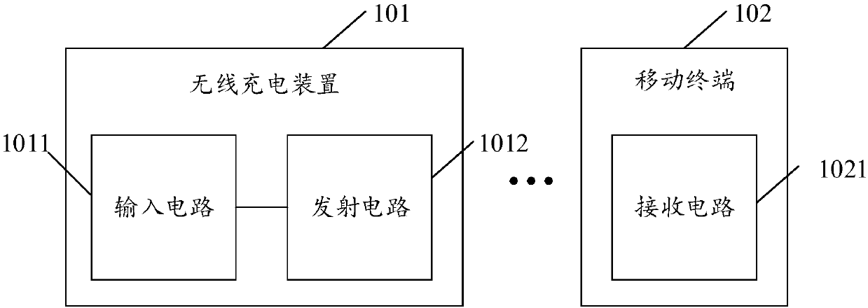
[0017] see figure 1 , figure 1 It is a structural schematic diagram of a wireless charging device in the prior art, such as figure 1 As shown, the wireless charging device 101 includes an input circuit 1011 and a transmitting circuit 1012 connected to each other. The input circuit 1011 is used to connect with a power source, specifically, the input circuit 1011 may be an adapter circuit, which is used to convert the mains power into a DC power and pr...


PUM


Abstract

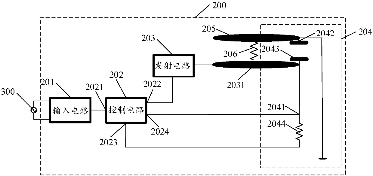
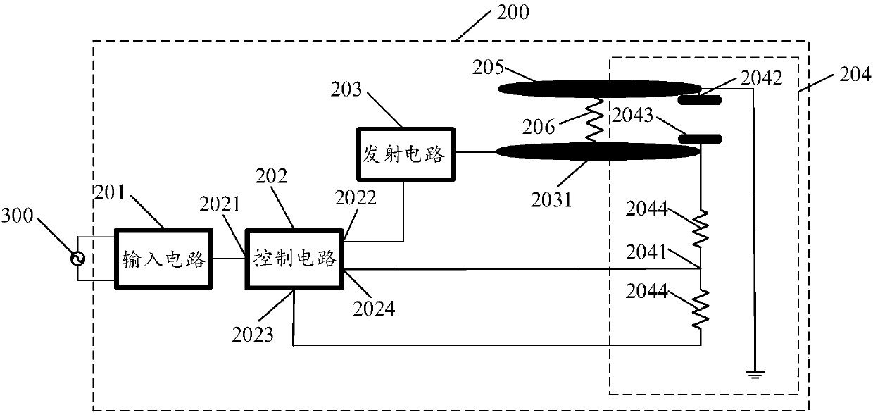
The invention provides a wireless charging device, and the device comprises an input circuit, a transmitting circuit, a control circuit and a detection circuit. The transmitting circuit comprises a transmitting coil. The device also comprises a placement board disposed above the transmitting coil, and the placement board is connected with the transmitting coil through an elastic element. The detection circuit comprises a first conductor disposed on the lower surface of the placement board, a second conductor which is disposed on the upper surface of the transmitting coil, and at least one load. The first conductor is grounded, and the second conductor is in series connection with at least one load. The detection circuit detects whether there is an object on the placement board or not. Thecontrol circuit controls the transmitting circuit to be cut off when there is no object on the placement board. Therefore, the device can cut off the transmitting circuit under the no-load condition,effectively reduces the energy loss of the transmitting circuit, and reduces the standby loss.

Description

technical field [0001] The present invention relates to the technical field of wireless charging, in particular to a wireless charging device. Background technique [0002] As the functions of mobile terminals (such as smart phones, tablet computers, etc.) become more and more powerful, the use of the mobile terminals becomes more and more frequent, so that the standby time of the mobile terminals becomes shorter and shorter, and the charging becomes more and more frequent. Wireless charging has become a mainstream trend of charging technology. Wireless charging can charge mobile terminals without using charging cables, and can provide greater convenience for charging mobile terminals. [0003] The transmitting circuit of the wireless charging device converts direct current into alternating current, and transmits the energy to the receiving end of the mobile terminal through the transmitting coil. DC power is used by mobile terminals. However, in the prior art, the transmi...

Claims


Application Information

Patent Timeline
Patent Type & Authority Applications(China)
IPC IPC(8): H02J50/60G01V3/02H02J7/00
CPCH02J50/60G01V3/02H02J7/025
Inventor 郭朋飞
Owner VIVO MOBILE COMM CO LTD
Learn More