
DC charging pile charging method based on module maximum current output and shift

A DC charging pile, maximum current technology, applied in transportation and packaging, battery circuit devices, current collectors, etc., can solve the problems of poor operation status of the charging module, shortened working life of the module, and high power factor, to reduce standby loss, The effect of improving working life and reducing maintenance costs

Active Publication Date: 2019-12-24
长园深瑞继保自动化有限公司 +1
View PDF4 Cites 0 Cited by
  • Summary
  • Abstract
  • Description
  • Claims
  • Application Information

AI Technical Summary

Problems solved by technology

Because the capacity of electric vehicles is not uniform, most DC charging piles are configured according to the maximum charging capacity of electric vehicles in order to meet the fast charging demand. Each charging module is not running at full load when the pile is charging the car
The DC charging modules in the charging power supply industry have the highest efficiency, the smallest harmonics, and the highest power factor at the maximum current output. Therefore, the charging modules working under the condition of partial load are not in good condition at this time. Will shorten the working life of the module

Method used


Image

  • DC charging pile charging method based on module maximum current output and shift
  • DC charging pile charging method based on module maximum current output and shift

Examples


Embodiment Construction

[0018] Below in conjunction with embodiment the present invention is further described.

[0019] A DC charging method based on module maximum current output and shift, comprising the following steps:

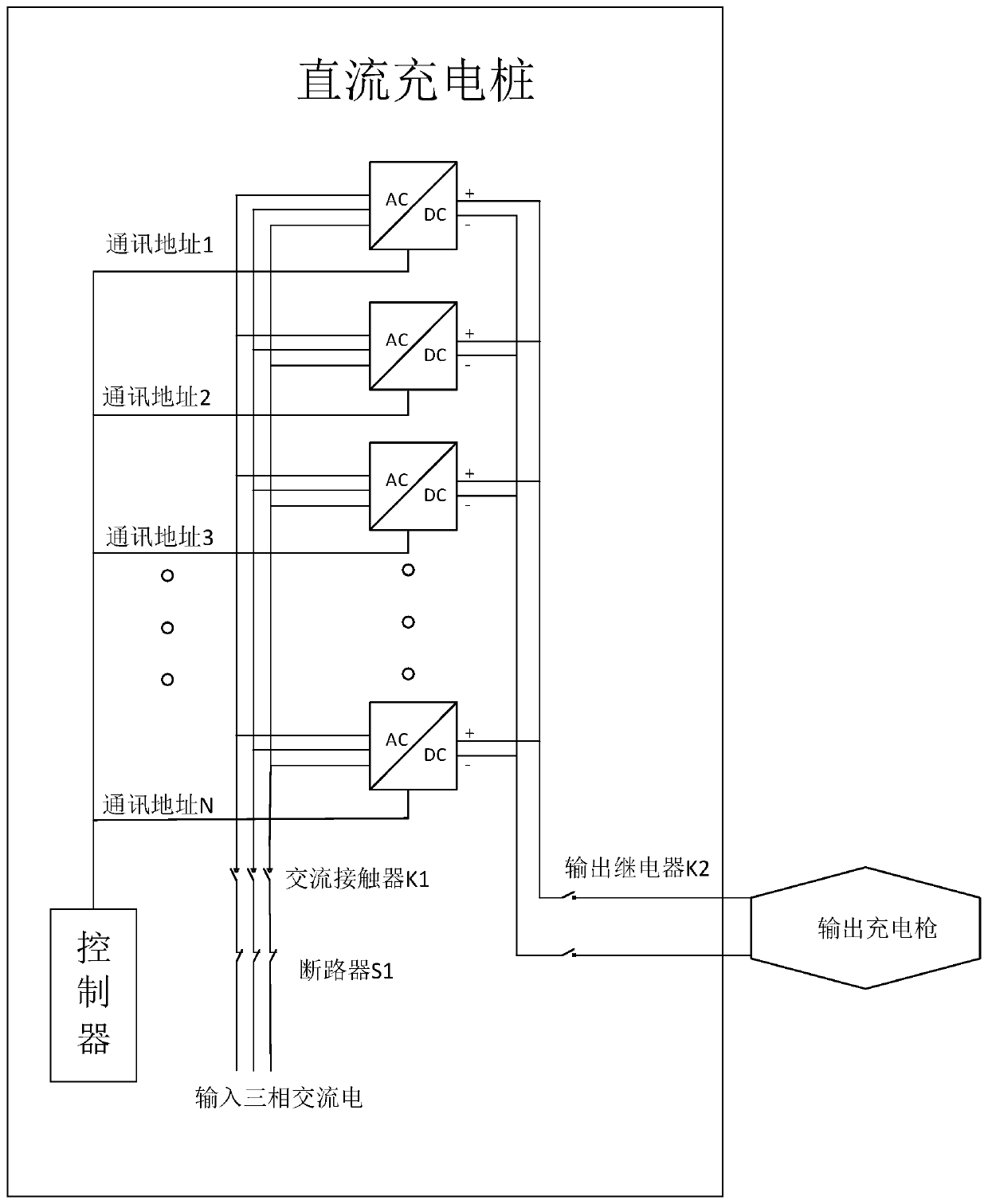
[0020] A. The DC charging pile is equipped with M charging modules, and the charging modules are connected in parallel. The AC input terminal of the charging module is connected to the electrical circuit, and the DC output terminal of the charging module is connected to the DC output circuit; the three-phase alternating current passes through the circuit breaker S1 and The AC contactor K1 is connected to the electrical circuit, and the charging pile S1 that is put into use is closed. When the charging gun of the DC charging pile is inserted into the charging interface of the electric vehicle, the AC contactor K1 is closed. When the charging stops, K1 is disconnected to reduce the number of charging modules. standby loss;

[0021] B. The main controller of the DC charging pile a...


PUM


Abstract

A direct current charging pile charging method based on the module maximum current output and alternate rest comprises: and calculating the module maximum output current Imax in the required voltage according to the constant power curve of a single charging module, wherein the charging module number required being put into Num=IBCL / Imax, the minimum module communication address in the work modules is recorded through the charging pile, and the charging piles of the other modules stops work for rest. According to the algorithm mentioned above, the modules put into work starts from the next address recorded at the last time when the next charging is started. The direct current charging pile charging method based on the module maximum current output and alternate rest can reduce the standby loss of the charging piles, improve the operation efficiency of the charging piles and reduce the waste of electric power and the cost of users. Less harmonic wave and improved power factors can reduce the pollution in the electric energy, and the module alternate rest improves the service life of the modules and reduces the maintenance cost.

Description

technical field [0001] The invention relates to a method in which the charging module of a DC charging pile operates at the maximum current output and at the same time ensures that the charging module takes turns. Background technique [0002] With the deepening of the global energy crisis, the depletion of oil resources and the increasing harm of air pollution and global temperature rise, governments and automobile companies in various countries generally recognize that energy saving and emission reduction are the main direction of future automobile technology development. The development of electric vehicles will It is the best way to solve these two technical difficulties, and charging piles, as the necessary infrastructure for the development of electric vehicles, have also ushered in explosive development this year. [0003] At present, the DC charging piles on the market have a large standby loss, resulting in a large waste of electric energy when not charging. The roo...

Claims


Application Information

Patent Timeline
Patent Type & Authority Patents(China)
IPC IPC(8): H02J7/00
CPCH02J7/0086
Inventor 许青松祖连兴陈锐陈加杰王汝泉
Owner 长园深瑞继保自动化有限公司
Learn More