
Energy storage apparatus and charge control method for the same

A charging control method and a technology of an electric storage device, which are applied in the direction of circuit devices, battery circuit devices, battery overcharge protection, etc., can solve problems such as low charging voltage, and achieve the effect of preventing the voltage from becoming high

Pending Publication Date: 2018-02-16
GS YUASA INT LTD
View PDF7 Cites 1 Cited by
  • Summary
  • Abstract
  • Description
  • Claims
  • Application Information

AI Technical Summary

Problems solved by technology

[0006] In addition, regarding this storage system, although the charging voltage of the lead storage battery is set at, for example, 14.8 [V] depending on the difference in battery characteristics, the charging voltage of the lithium ion battery is set at, for example, 14 [V]. The charging voltage is set lower than that of lead-acid batteries
[0007] However, since the shape of the main body of the power storage system and the shape of the communication connector are the same as those of the lead-acid battery, there is a possibility that the lithium-ion battery will be charged by the charger for the lead-acid battery. If the rechargeable lead-acid battery is charged with a charger, even if the battery voltage exceeds the allowable charging range, it will still be charged, and it will become an overcharged state.

Method used


Image

  • Energy storage apparatus and charge control method for the same
  • Energy storage apparatus and charge control method for the same
  • Energy storage apparatus and charge control method for the same

Examples


Embodiment approach

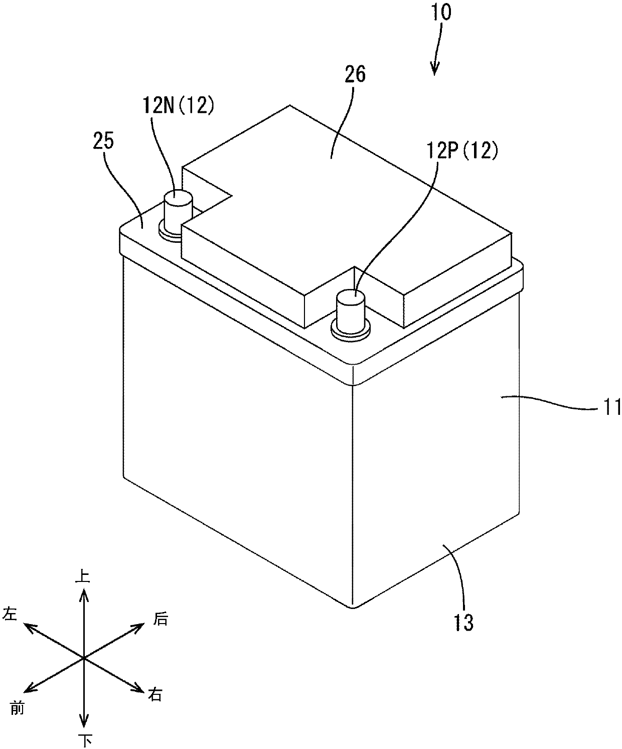
[0048] refer to Figure 1 to Figure 9 An embodiment in which the technology disclosed in this specification is applied to the power storage device 10 for starting the engine of a vehicle such as an automobile will be described.

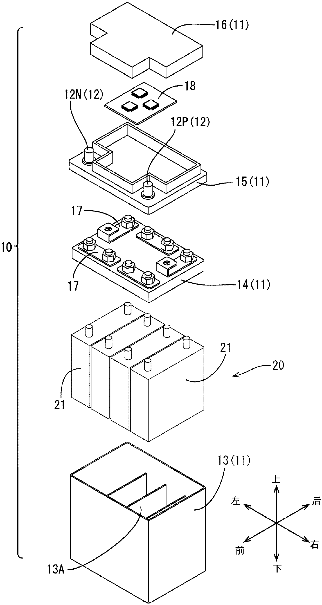
[0049] like figure 1 As shown, the power storage device 10 has a block-shaped battery case 11 . like figure 2 As shown, a battery pack 20 in which a plurality (four in this embodiment) of power storage elements 21 are connected in series, a control board 18 , and the like are housed in the battery case 11 .

[0050] In addition, in the following description, when referring to figure 1 as well as figure 2 In the case of , the up-down direction is based on the up-down direction of the battery case 11 when the battery case 11 is placed horizontally without inclination relative to the installation surface, and the front-rear direction is based on the direction along the short side portion of the battery case 11 (depth direction). ) as a reference, le...


PUM


Abstract

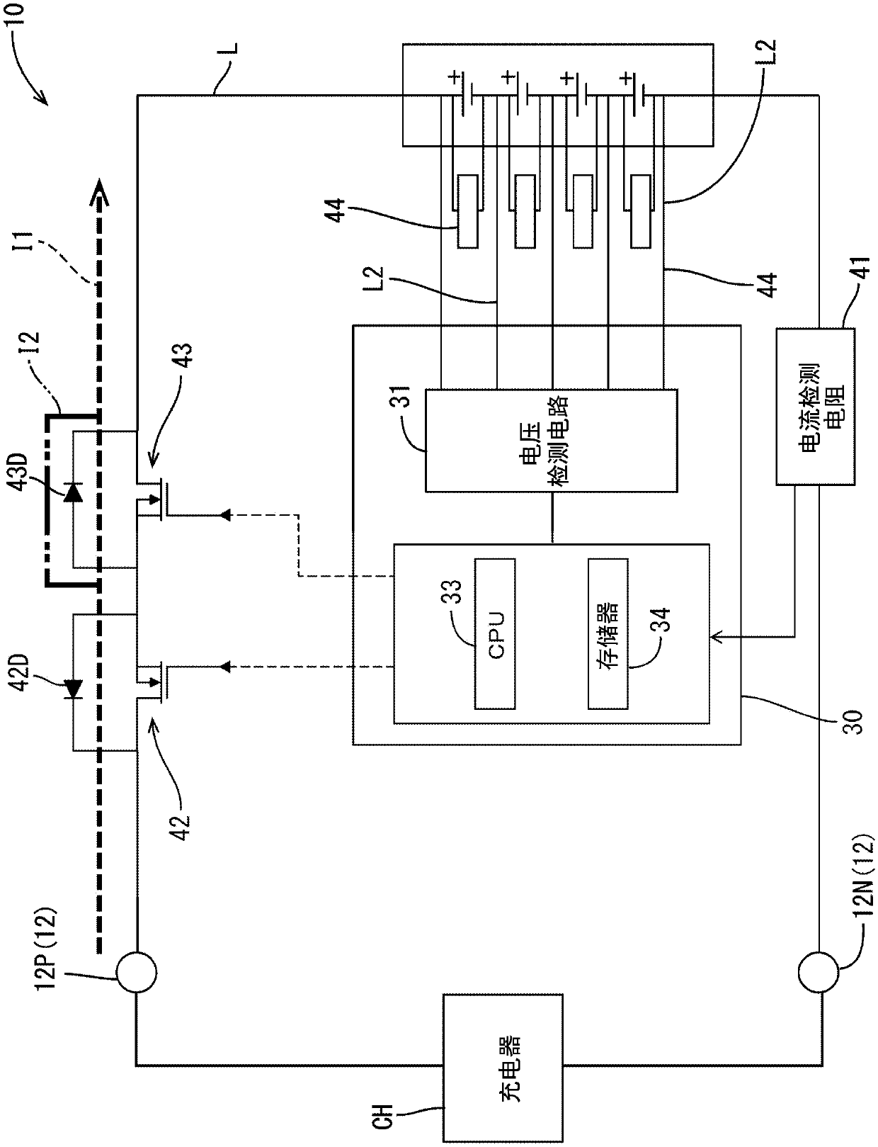
The present invention provides a power storage apparatus and a charge control method for the same. Even if the charging is performed at a charging voltage higher than the assumed charging voltage, itis possible to continue charging without causing an inconvenience. The energy storage apparatus (10) includes an assembled battery (20) including a plurality of energy storage devices (21), a discharge shutoff device (43) incorporating a parasitic diode (43D), configured to switch a path of a charge to the assembled battery to a path through the parasitic diode, a voltage detection circuit (31) configured to detect a cell voltage of the energy storage device (21) and a battery voltage of the assembled battery (20), and a battery management unit (30). When the cell voltage in at least one energy storage device among the plurality of energy storage devices (21) is higher than a full charge voltage and equal to or more than an equalization start threshold value lower than an overcharge voltage, a CPU (33) of the battery management unit (30) switches a path of the charge to the assembled battery (20) to a path through the parasitic diode (43D) with the discharge shutoff device (43).

Description

technical field [0001] The technology disclosed in this specification relates to a power storage device and a charging control method for the power storage device. Background technique [0002] For example, Japanese Patent Application Laid-Open No. 2014-225942 is known as an electric storage system for engine starting of a vehicle. In this power storage system, secondary batteries that can be reduced in size and weight compared to lead batteries, such as lithium ion batteries, are used instead of lead batteries. [0003] prior art literature [0004] patent documents [0005] Patent Document 1: Japanese Patent Laid-Open No. 2014-225942 [0006] In addition, regarding this storage system, although the charging voltage of the lead storage battery is set at, for example, 14.8 [V] depending on the difference in battery characteristics, the charging voltage of the lithium ion battery is set at, for example, 14 [V]. The charging voltage is set lower than that of the lead stora...

Claims


Application Information

Patent Timeline
IPC IPC(8): H02J7/00
CPCH02J7/0026H02J7/0029H02J7/0031H02J7/0036H02J7/00302H01M10/48H01M10/482H01M10/0525H01M10/441H02J7/0016H02J7/00306Y02E60/10H01M10/425H01M2010/4271H01M2220/20
Inventor 白石刚之
Owner GS YUASA INT LTD
Learn More