
Display panel and driving method thereof

A technology of a display panel and a driving method, which is applied to static indicators, instruments, etc., can solve the problems of reducing the display effect of the display panel and changing the characteristics.

Active Publication Date: 2018-02-16
SHANGHAI AVIC OPTOELECTRONICS
View PDF8 Cites 5 Cited by
  • Summary
  • Abstract
  • Description
  • Claims
  • Application Information

AI Technical Summary

Problems solved by technology

However, after the current display panel lowers the display driving frequency, the thin film transistors in the display panel that control the potential maintenance of the electrode electrodes of each pixel will be in the state of low voltage bias or high voltage bias for a long time, and the thin film transistors will be biased for a long time. Make its characteristics change, thereby reducing the display effect of the display panel

Method used


Image

  • Display panel and driving method thereof
  • Display panel and driving method thereof
  • Display panel and driving method thereof

Examples


Embodiment Construction

[0015] The application will be further described in detail below in conjunction with the accompanying drawings and embodiments. It should be understood that the specific embodiments described here are only used to explain related inventions, rather than to limit the invention. It should also be noted that, for ease of description, only parts related to the invention are shown in the drawings.

[0016] It should be noted that, in the case of no conflict, the embodiments in the present application and the features in the embodiments can be combined with each other. The present application will be described in detail below with reference to the accompanying drawings and embodiments.

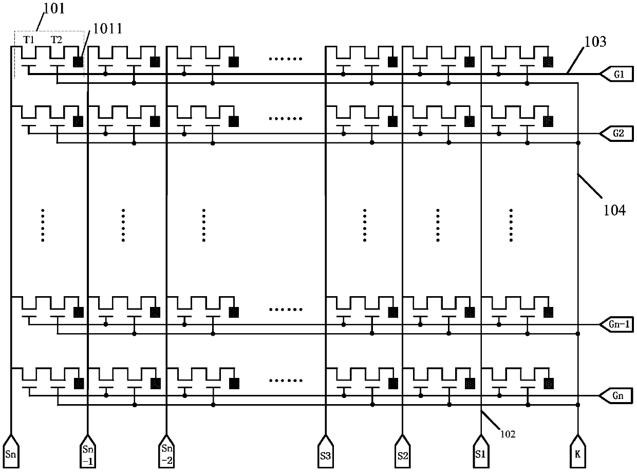
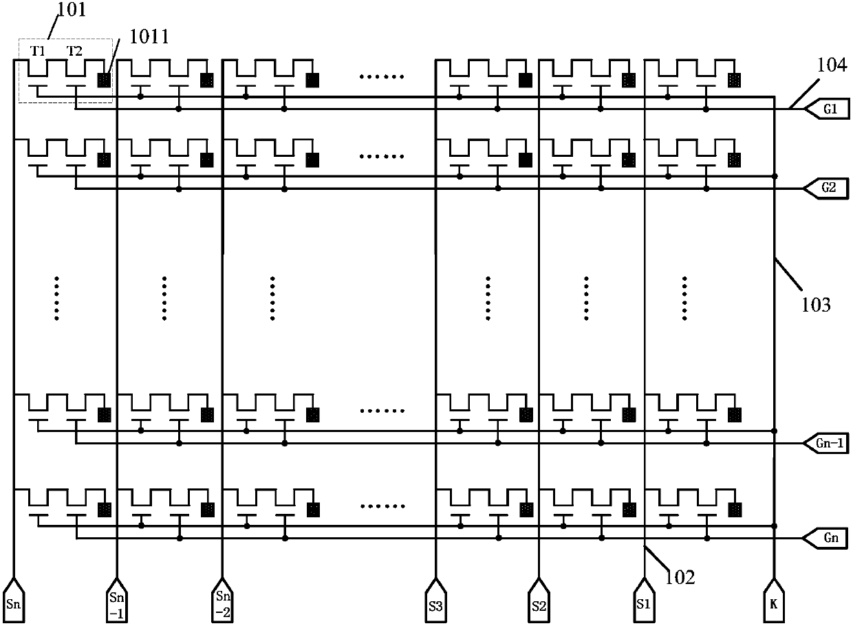
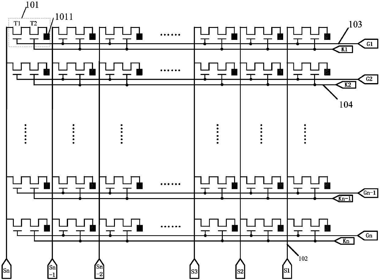
[0017] Figure 1A A schematic structural diagram of an embodiment of a display panel according to the present application is shown. The display panel provided in this embodiment may include a plurality of pixel unit groups, and each pixel unit group may include a plurality of pixel units 101. For ...


PUM


Abstract

The application discloses a display panel and a driving method thereof, and belongs to the display technology field. The display panel comprises a plurality of pixel unit sets, each pixel unit set comprises a plurality of pixel units, and a pixel electrode and a thin film transistor set are arranged in each pixel unit. Each thin film transistor set at least comprises a first thin film transistor and a second thin film transistor. The first pole of the first thin film transistor is electrically connected with a data line, the second pole is connected with the first pole of the second thin filmtransistor electrically, and the grid is connected with a first grid control signal line electrically. The second pole of the second thin film transistor is connected with the pixel electrode, and thegrid is connected with a second grid control signal line electrically. The above display panel controls the time-sharing conduction of the first and second thin film transistors in the thin film transistor sets to keep the sustaining voltages of the pixel electrodes, thereby avoiding the situation that the thin film transistors are biased for a long time, so that the characteristics change.

Description

technical field [0001] The present application relates to the field of display technology, in particular to a display panel and a driving method for driving the display panel. Background technique [0002] With the development of display technology, the display effect of display products is continuously improved, so that liquid crystal display products and the like are more and more widely used. [0003] The power consumption of the display panel is directly proportional to the display driving frequency. In order to reduce the power consumption of the display panel, the display driving frequency needs to be reduced. However, after the current display panel lowers the display driving frequency, the thin film transistors in the display panel that control the potential maintenance of the electrode electrodes of each pixel will be in the state of low voltage bias or high voltage bias for a long time, and the thin film transistors will be biased for a long time. The characterist...

Claims


Application Information

Patent Timeline
Patent Type & Authority Applications(China)
IPC IPC(8): G09G3/36
CPCG09G3/3648
Inventor 席克瑞崔婷婷
Owner SHANGHAI AVIC OPTOELECTRONICS
Learn More