Power balancing machine

A dynamic balancing and movable sleeve technology, applied in the field of mechanical equipment and dynamic balancing machine equipment, can solve the problems of poor protection of the dynamic balancing machine, insufficient fixing, affecting the measurement effect, etc. effect of work

Inactive Publication Date: 2018-02-16
十堰市宏昌达工贸股份有限公司
View PDF0 Cites 0 Cited by
  • Summary
  • Abstract
  • Description
  • Claims
  • Application Information

AI Technical Summary

Problems solved by technology

[0005] In order to solve the above technical problems, the present invention provides a dynamic balancing machine to solve the problem that when the existing dynamic balancing machine is in use, the fixation is not tight enough, and the detected items are easily thrown away during rotation, which affects the measurement effect, and when the power When the balancing machine is started, the protection around the dynamic balancing machine is poor. If other personnel touch the running dynamic balancing machine, it is easy to cause personal injury.

Method used


Image

  • Power balancing machine
  • Power balancing machine
  • Power balancing machine

Examples


Embodiment

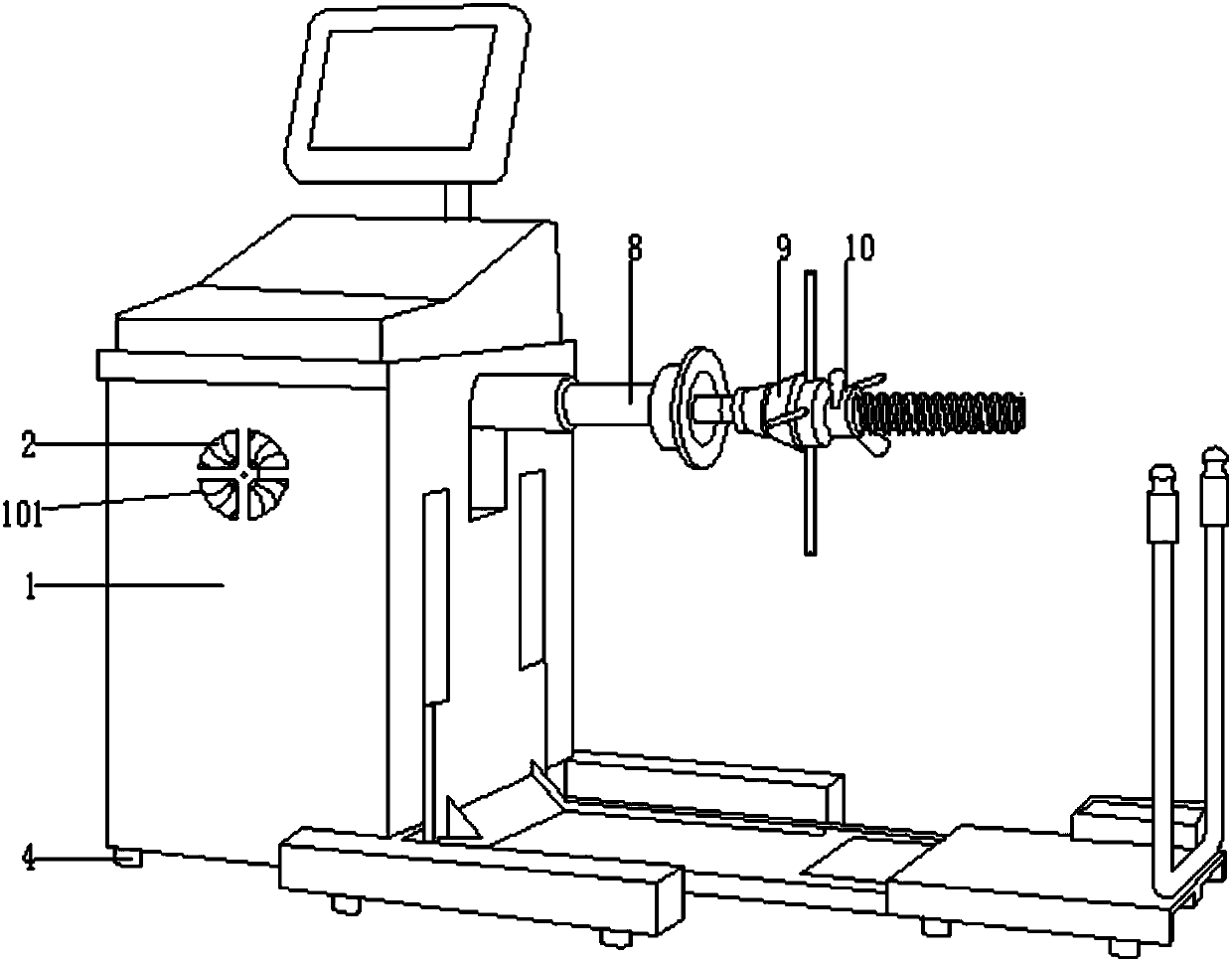
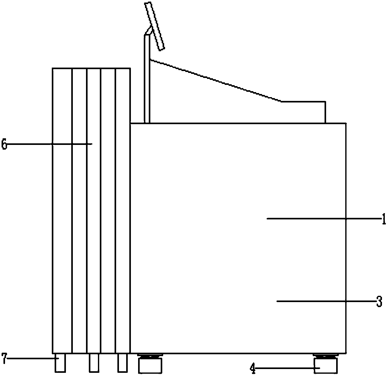
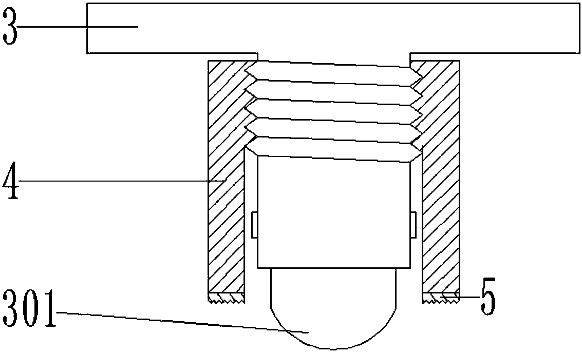
[0025] as attached figure 1 to attach Figure 5 Shown:

[0026] The present invention provides a power balancing machine, including a power balancing machine 1, a vent 101, an exhaust fan 2, a support column 3, a roller 301, a movable sleeve 4, a protective rubber pad 5, a transparent plate 6, a universal wheel 7, a rotating shaft 8, Fixed block 9 and locking block 10, described exhaust fan 2 is two places, and two exhaust fans 2 are all installed on the body wall of power balancing machine 1, and exhaust fan 2 is connected with the power line that power balancing machine 1 inside is provided with, so The support column 3 is located at the bottom of the dynamic balancing machine 1, and a roller 301 is installed at the bottom of the support column 3, and the outer end surface of the support column 3 is a self-locking external thread structure, the movable sleeve 4 is a tubular structure, and the bottom of the movable sleeve 4 A protective rubber pad 5 is installed, and the in...


PUM


Abstract

The invention provides a dynamic balancing machine, which includes a dynamic balancing machine, a vent, an exhaust fan, a support column, a roller, a movable sleeve, a protective rubber pad, a transparent plate, a roller, a rotating shaft, a fixed block and a locking block, and the exhaust fan has two , and the two exhaust fans are installed on the body wall of the dynamic balancing machine, and the exhaust fan is connected to the power line provided inside the dynamic balancing machine. The support column is located at the bottom of the dynamic balancing machine, and a roller is installed at the bottom of the support column. It is beneficial to protect the inside of the dynamic balancing machine, avoiding excessive internal temperature of the dynamic balancing machine, causing damage to the transmission system and affecting the monitoring efficiency of the staff, and with the setting of the transparent plate, the dynamic balancing machine can be in contact with the outside world during rotation measurement They are isolated from each other to prevent other personnel from touching the fast-rotating detection objects and causing personal injury, and the setting of the transparent plate hinge is conducive to reducing the space occupation rate and making it more convenient for personnel to retract and unfold.

Description

technical field [0001] The invention belongs to the technical field of dynamic balancing machine equipment and mechanical equipment, and in particular relates to a dynamic balancing machine. Background technique [0002] The balancing machine is an instrument used to measure the unbalance of the rotor. The balancing machine belongs to the hard-supported balancing machine. The vibration on the bearing is reduced to the allowable range to achieve the purpose of reducing vibration, improving performance and improving product quality. [0003] Based on the above, when the inventor visited the staff operating the power balancing machine for a long time, he found that the existing power balancing machine was not fixed tightly enough when it was in use, and it was easy to throw the detected items flying when rotating, which affected the measurement effect, and when the power When the balancing machine is started, the protection around the dynamic balancing machine is poor. If othe...

Claims


Application Information

Patent Timeline
Patent Type & Authority Applications(China)
IPC IPC(8): G01M1/38G01M1/02G01M1/04
CPCG01M1/16G01M1/02G01M1/04
Inventor 胡玉梅胡军
Owner 十堰市宏昌达工贸股份有限公司
Why Eureka
Try Eureka