
Roller drying machine

A technology of drum dryer and outer drum, applied in dryers, biomass drying, drying of solid materials, etc., can solve the problems of high use cost of the dryer, the materials are not dried well, and the drying is uneven, and the drying effect can be improved. , Improve drying uniformity, better drying effect

Inactive Publication Date: 2018-02-16
遵义双河生物燃料科技有限公司
View PDF8 Cites 2 Cited by
  • Summary
  • Abstract
  • Description
  • Claims
  • Application Information

AI Technical Summary

Problems solved by technology

[0004] However, there are still certain defects in the above-mentioned technical scheme: 1. The materials to be dried are scattered in the drum, and they are turned over in the drum following the rotation of the drum, which may easily cause partial drying and uneven drying. The material close to the drum wall is over-dried; 2. It is necessary to blow flowing hot air into the drum separately, and also use the power mechanism to drive the drum to rotate, which wastes electricity and the use cost of the dryer is high

Method used


Image

  • Roller drying machine

Examples


Embodiment Construction

[0017] The present invention will be described in further detail below by means of specific embodiments:

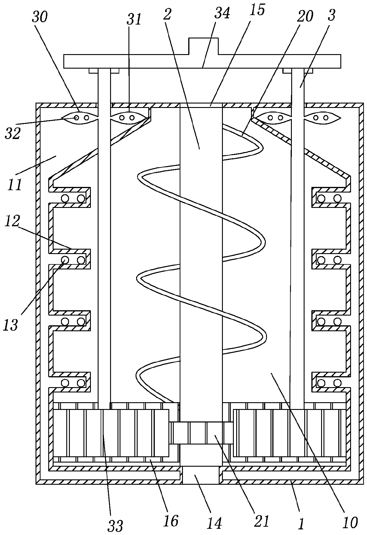
[0018] The reference signs in the drawings of the specification include: outer drum 1, drying chamber 10, interlayer 11, protrusion 12, air outlet 13, feed inlet 14, outlet 15, inner ring gear 16, inner drum 2, spiral blade 20, central gear 21, rotating cylinder 3, left blade 30, right blade 31, jet hole 32, circumferential gear 33, air intake box 34.

[0019] A tumble dryer, such as attached figure 1 As shown, it includes an outer drum 1 with a drying chamber 10, the bottom of the outer drum 1 is provided with a feed port 14, the top of the outer drum 1 is provided with a discharge port 15, and an inner drum 2 and a hollow rotating drum 3 are also included; The side wall of the drum 1 is provided with a hollow interlayer 11, and the side wall of the outer drum 1 is provided with an air outlet 13 for communicating with the interlayer 11 and the drying chamber 10, and the...


PUM


Abstract

The invention relates to the technical field of solid fuel manufacturing, in particular to a roller drying machine. The roller drying machine comprises an outer roller with a drying cavity, a feedingport is formed in the bottom of the outer roller, and a discharging port is formed in the top of the outer roller. The roller drying machine further comprises an inner roller and a hollow rotation barrel. A hollow interlayer is arranged on the side wall of the outer roller, air outlet holes through which the interlayer communicates with the drying cavity are formed in the side wall of the outer roller, and an inner gear ring is arranged at the bottom of the outer roller. The inner roller is provided with a spiral blade, wherein one end of the spiral blade communicates with the feeding port, and the other end of the spiral blade communicates with the discharging port. A center gear is arranged at the bottom of the inner roller. An air inlet is formed in one end of the rotation barrel, and aleft blade and a right blade are symmetrically arranged on the rotation barrel. Air injection holes are formed in the front end face of the left blade, air injection holes are formed in the rear endface of the right blade, and a circumferential gear is arranged at the bottom of the rotation barrel and engaged with the inner gear ring and the center gear. By adoption of the technical scheme, thematerial drying uniformity can be improved while power energy consumption can be reduced.

Description

technical field [0001] The invention relates to the technical field of solid fuel production, in particular to a drum dryer. Background technique [0002] Traditional agricultural and forestry residues are used as fuel, such as straw, etc. The most common burning method is direct combustion. This method not only produces waste gas and smoke, which affects the environment, but also has a short burning time and does not make full use of agricultural and forestry residues. For this reason, a kind of "biomass briquette fuel" has appeared in recent years, which is a clean and low-carbon renewable energy source. No pollution to the environment. Specifically, in the production of biomass briquettes, the current methods mostly use agricultural and forestry residues as the main raw material, after slicing, crushing, impurity removal, fine powder, screening, mixing, softening, tempering, extrusion, drying, Cooling, quality inspection, packaging and other processes, and finally made ...

Claims


Application Information

Patent Timeline
IPC IPC(8): F26B17/00F26B25/16F26B25/04F26B21/00
CPCF26B17/00F26B21/004F26B25/04F26B25/16F26B2200/02
Inventor 申朝兴
Owner 遵义双河生物燃料科技有限公司
Learn More