
Material storing device having cooling and heat dissipation structure and working method thereof

A heat dissipation structure and material storage technology, applied in fruit hanging devices, botanical equipment and methods, anti-corrosion coatings, etc., can solve the problems affecting the cooling and heat dissipation effect of granaries, the uncontrollable external air temperature, applicability and practical limitations, etc. , to achieve good practicability, improve ventilation and heat dissipation performance, and compact structure

Inactive Publication Date: 2018-02-16
卞毓平
View PDF6 Cites 4 Cited by
  • Summary
  • Abstract
  • Description
  • Claims
  • Application Information

AI Technical Summary

Problems solved by technology

[0002] The storage device is a structure used to store items, such as granaries, barns, etc. It is mainly composed of a warehouse body and an air duct arranged on the warehouse body. A fan is installed in the air duct, which mainly uses the fan to make the external low-temperature air Grain stacks are used to reduce the temperature in the warehouse. At the same time, fumigation and insecticide are also used to increase the storage time of grain. However, because the fan makes the external air flow to achieve cooling, but because the temperature of the external air cannot be controlled, it will affect the grain warehouse. The effect of cooling and heat dissipation is limited, so the applicability and practicality are limited

Method used


Image

  • Material storing device having cooling and heat dissipation structure and working method thereof

Examples


Embodiment 1

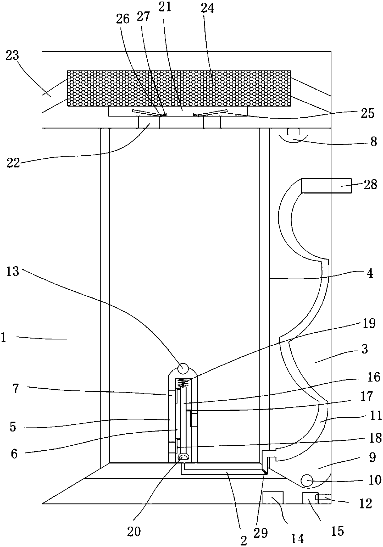
[0021] Such as figure 1 The shown material storage device with a cooling and heat dissipation structure includes a bin body 1, an air passage 2 arranged on the bin body 1, a cavity 3 is provided in the side wall of the bin body 1, and a cavity 3 is arranged in the side wall of the bin body 1. A heat insulation board 4 is arranged in the cavity 3, a vertical pole 5 is evenly arranged on the bottom wall of the warehouse body 1, and a guide tube communicating with the air passage 2 is arranged in the vertical pole 5. The wind channel 6 is provided with an air hole 7 communicating with the air guide channel 6 on the vertical pole 5, and a water spray nozzle 8 is provided on the top wall of the cavity 3. A water collection chamber 9 is arranged on the bottom wall of the chamber 3, and a water pump 10 is fixed in the water collection chamber 9, and the water pump 10 is connected with the water nozzle 8, and a spiral Shaped air guide pipe 11, one end of the spiral air guide pipe 11 ...

Embodiment 2

[0028] Such as figure 1The shown material storage device with a cooling and heat dissipation structure includes a bin body 1, an air passage 2 arranged on the bin body 1, a cavity 3 is provided in the side wall of the bin body 1, and a cavity 3 is arranged in the side wall of the bin body 1. A heat insulation board 4 is arranged in the cavity 3, a vertical pole 5 is evenly arranged on the bottom wall of the warehouse body 1, and a guide tube communicating with the air passage 2 is arranged in the vertical pole 5. The wind channel 6 is provided with an air hole 7 communicating with the air guide channel 6 on the vertical pole 5, and a water spray nozzle 8 is provided on the top wall of the cavity 3. A water collection chamber 9 is arranged on the bottom wall of the chamber 3, and a water pump 10 is fixed in the water collection chamber 9, and the water pump 10 is connected with the water nozzle 8, and a spiral Shaped air guide pipe 11, one end of the spiral air guide pipe 11 i...

Embodiment 3

[0035] Such as figure 1 The shown material storage device with a cooling and heat dissipation structure includes a bin body 1, an air passage 2 arranged on the bin body 1, a cavity 3 is provided in the side wall of the bin body 1, and a cavity 3 is arranged in the side wall of the bin body 1. A heat insulation board 4 is arranged in the cavity 3, a vertical pole 5 is evenly arranged on the bottom wall of the warehouse body 1, and a guide tube communicating with the air passage 2 is arranged in the vertical pole 5. The wind channel 6 is provided with an air hole 7 communicating with the air guide channel 6 on the vertical pole 5, and a water spray nozzle 8 is provided on the top wall of the cavity 3. A water collection chamber 9 is arranged on the bottom wall of the chamber 3, and a water pump 10 is fixed in the water collection chamber 9, and the water pump 10 is connected with the water nozzle 8, and a spiral Shaped air guide pipe 11, one end of the spiral air guide pipe 11 ...


PUM


Abstract

The invention discloses a material storing device having a cooling and heat dissipation structure and a working method thereof. A dustproof cover comprises a bin body, a ventilation channel is formedin the bin body, a cavity is formed in the side wall of the bin body, a heat insulation plate is arranged in the cavity, a vertical columnar rod is uniformly arranged on the bottom wall of the bin body, an air guiding channel is formed in the vertical columnar rod, an air hole communicated with the air guiding channel is formed in the vertical columnar rod, a water spraying nozzle is formed in thetop wall of the cavity, a water collecting cavity is formed in the bottom wall of the cavity, a spiral air guiding pipe is arranged in the cavity, a power line connected with a water pump is arrangedon the bin body, a temperature sensor is fixed to the outer wall of the vertical columnar rod of the bin body, and a driver connected with the temperature sensor is arranged on the bin body and is connected with a power switch of a water pump. The material storing device is reasonable in structural arrangement, can effectively prevent heat accumulation caused by exposure to the sun, facilitates prolonging of storage time, is stable and reliable in use and good in applicability and practicability, and meanwhile the ventilating and heat dissipation properties of the device are improved.

Description

technical field [0001] The invention belongs to the technical field of storage structures, and in particular relates to a material storage device with a cooling and heat dissipation structure and a working method of the material storage device with a cooling and heat dissipation structure. Background technique [0002] The storage device is a structure used to store items, such as granaries, barns, etc. It is mainly composed of a warehouse body and an air duct arranged on the warehouse body. A fan is installed in the air duct, which mainly uses the fan to make the external low-temperature air Grain stacks are used to reduce the temperature in the warehouse. At the same time, fumigation and insecticide are also used to increase the storage time of grain. However, because the fan makes the external air flow to achieve cooling, but because the temperature of the external air cannot be controlled, it will affect the grain warehouse. The effect of cooling and heat dissipation is ...

Claims


Application Information

Patent Timeline
IPC IPC(8): A01F25/14A01F25/22C09D133/00C09D5/08C09D5/14C09D7/61C09D7/63C09D7/65
CPCA01F25/14A01F25/22C08K2003/2241C08K2201/011C08K2201/014C08L2205/035C09D5/08C09D5/14C09D133/00C08L89/00C08L97/02C08L1/284C08K13/02C08K3/26C08K3/34C08K3/22C08K3/346
Inventor 卞毓平
Owner 卞毓平
Learn More