Directly connected drainpipe floor drain and its installation method

A technology for drainage pipes and floor drains, applied in water supply devices, drainage structures, waterway systems, etc., can solve problems such as floor seepage, achieve the effects of speeding up construction progress, avoiding openings, and reducing construction procedures

Active Publication Date: 2020-12-01
CHINA CONSTR EIGHT ENG DIV CORP LTD
View PDF5 Cites 0 Cited by
  • Summary
  • Abstract
  • Description
  • Claims
  • Application Information

AI Technical Summary

Problems solved by technology

To use this method for drainage, it is necessary to open corresponding holes for floor drains on the floor and holes for drain pipes to pass through the floor. A little carelessness in the waterproof construction of the location may easily cause water seepage on the floor

Method used


Image

  • Directly connected drainpipe floor drain and its installation method
  • Directly connected drainpipe floor drain and its installation method
  • Directly connected drainpipe floor drain and its installation method

Examples


Embodiment Construction

[0029] In order to facilitate the understanding of the present invention, the following will be described in conjunction with the accompanying drawings.

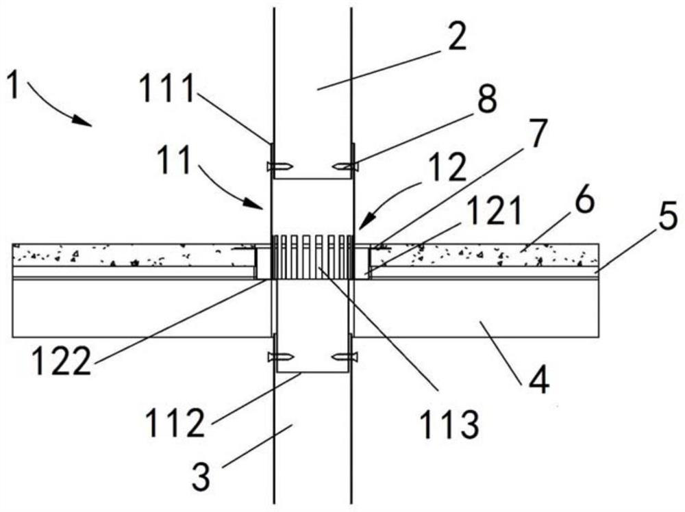
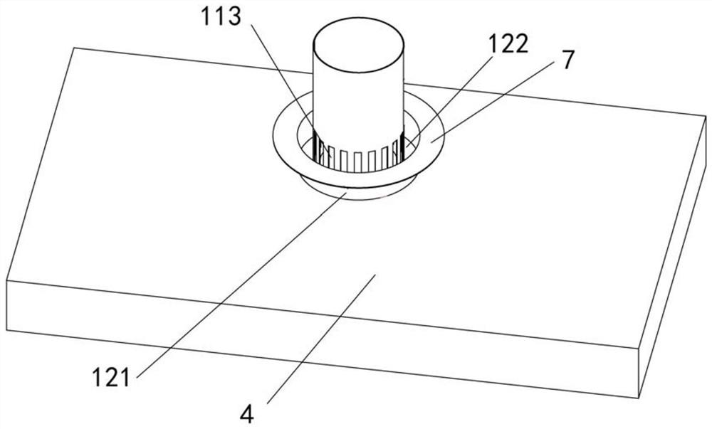
[0030] see figure 1 , figure 2 As shown, the present invention provides a floor drain directly connected to the drain pipe. The floor drain 1 is placed in the reserved drain pipe hole of the floor structure and connected to the upper drain pipe 2 located on the upper side of the floor structure and the drain pipe located on the floor structure. The lower drainpipe 3 on the lower side, the floor drain includes a body 11 and a supporting structure 12 .

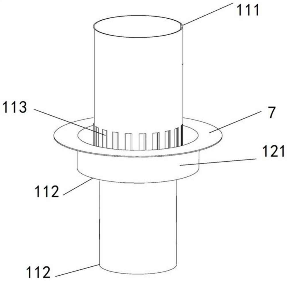
[0031] The body 11 is shaped like a cylinder and has an upper port 111 and a lower port 112, the upper port 111 is connected to the upper drain pipe 2, and the lower port 112 is connected to the lower drain pipe 3. ; The middle surface of the body 11 is provided with a leaking gate 113 extending axially along its cylindrical shape.

[0032] In the embodiment of the present...


PUM


Abstract

The invention provides a floor drain structure directly connected with a drain pipe and an installation method of the floor drain structure. The floor drain structure is placed in reserved drainage pipe holes of a floor slab structure in a penetrating mode; the floor drain includes a body and a support structure, the upper port and lower port of the body are communicated with an upper-portion drainage pipe and a lower-portion drainage pipe respectively, and the peripheral face of the middle section of the body is provided with a drainage gate opening extending in the axial direction of the cylindrical shape of the body; the support structure is arranged on the peripheral side of the drainage gate in a surrounding mode and located in the reserved drainage pipe holes of the floor slab, the bottom edge of the annular peripheral wall of the support structure is provided with an annular bottom wall, a water inlet of the floor drain is formed between the top edge of the annular peripheral wall and the body, and the annular peripheral wall, the annular bottom wall and the body are defined to form an annular drainage space. By the technological means, opening of a traditional floor drain position of the floor slab can be avoided, and the number of horizontal connection pipes between the traditional floor drain and the drainage pipes is reduced, the construction cost is reduced, the construction process is reduced and the construction progress is sped up.

Description

technical field [0001] The invention relates to the technical field of building construction, in particular to a floor drain directly connected to a drainage pipe and an installation method thereof. Background technique [0002] On the ground of traditional outdoor balconies with drainage requirements, a floor drain must be installed, and there is a certain distance between the floor drain and the drain pipe. Corresponding pipes must be used to connect the floor drain and the drain pipe to form a complete drainage system. To use this method for drainage, it is necessary to open corresponding holes for floor drains on the floor and holes for drain pipes to pass through the floor. If the waterproof construction of the location is a little careless, it is more likely to cause water seepage on the floor. Contents of the invention [0003] In view of the above situation, the present invention provides a floor drain directly connected to the drain pipe and its installation meth...

Claims


Application Information

Patent Timeline
Patent Type & Authority Patents(China)
IPC IPC(8): E03F5/04
CPCE03F5/0407E03F5/0409E03F5/041
Inventor 张彦奇陈笑凯亓立刚崔爱珍
Owner CHINA CONSTR EIGHT ENG DIV CORP LTD
Why Eureka
Try Eureka