
Lifting working platform

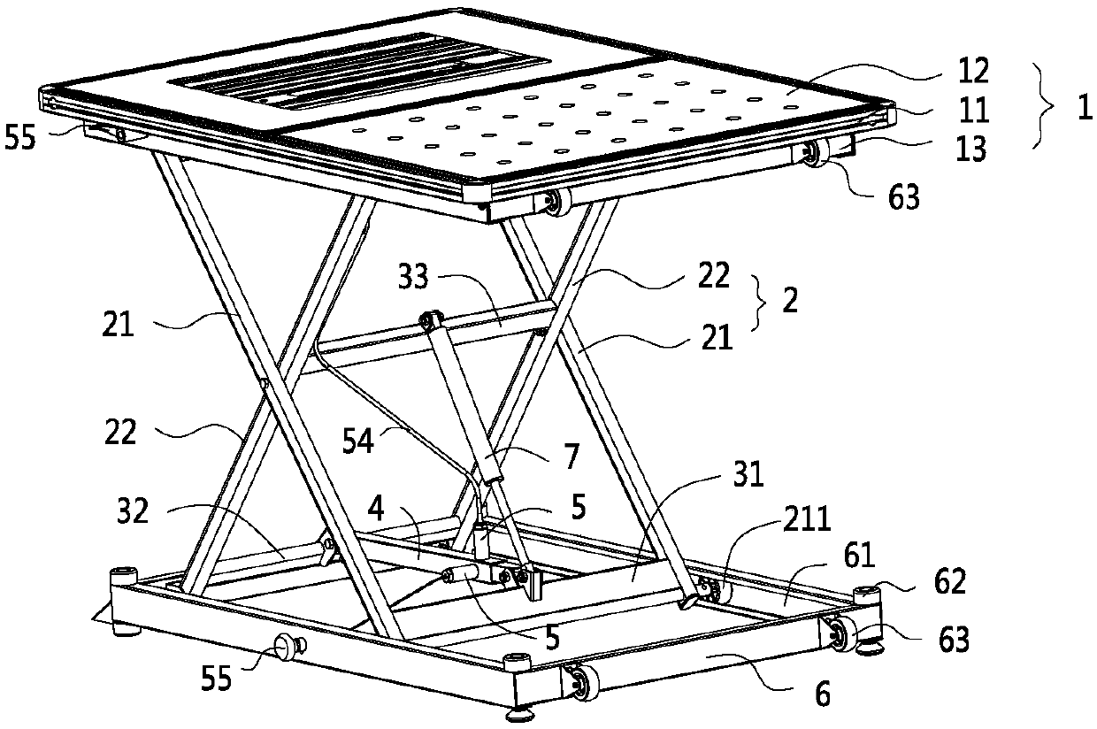
A technology for raising and lowering workbenches and operating platforms, which is applied in the direction of lifting frames and lifting devices, which can solve the problems of high manufacturing cost, inconvenient, and affecting work efficiency, and achieve the effect of low cost, simple structure, and good coordination

Active Publication Date: 2018-02-13
JINHUA ZHENFEI TOOLS
View PDF9 Cites 4 Cited by
  • Summary
  • Abstract
  • Description
  • Claims
  • Application Information

AI Technical Summary

Problems solved by technology

[0002] In some manufacturing enterprises, a series of manufacturing processes such as welding, grinding, drilling, etc. are usually encountered. Such manufacturing processes require a workbench to facilitate the placement of fixtures, processing equipment, etc., but in traditional enterprises This type of workbench is fixed. If the fixtures, processing equipment, and height of the operator are different, it will often cause the operator to become very uncomfortable and inconvenient when actually operating. Seriously affect work efficiency
[0003] In view of this, workbenches that can be raised and lowered have also appeared on the existing market. However, such elevating workbenches usually can only stop at the lowest position and the highest position, and can rarely hover in the middle position. Usually, driving devices such as motors or oil cylinders are used, and the self-locking function of this type of equipment is used to achieve hovering. The manufacturing cost of this type of equipment is generally high, and the structure is relatively complicated, so the popularity rate in enterprises will be low. greatly affected

Method used


Image

  • Lifting working platform
  • Lifting working platform
  • Lifting working platform

Examples


Embodiment 2

[0069] The difference from Embodiment 1 is that one side of the lifting fork in Embodiment 1 is fixedly hinged with the operating platform and the base, while in this embodiment the entire lifting fork is slidingly connected with the operating platform and the base, that is, the first The top end of the first fork rod is slidably connected with the operation platform, and the bottom end is slidably connected with the base; the top end of the second fork rod is slidably connected with the operation platform, and the bottom end is slidably connected with the base.

Embodiment 3

[0071] The difference from Embodiment 1 is that in this embodiment, the first connecting rod and the lifting fork, and the second connecting rod and the lifting fork are all rotationally connected, that is, the first connecting rod and the first fork The rods are connected in rotation, the second connecting rod is connected in rotation with the second fork rod, and the bushing is fixedly connected with the first connecting rod and the second connecting rod.

[0072] The third connecting rod can be selected to be rotationally connected with the second fork rod, while the telescopic element is fixedly connected with the third connecting rod. Fixedly connected, the telescopic element is hinged with the third connecting rod.


PUM


Abstract

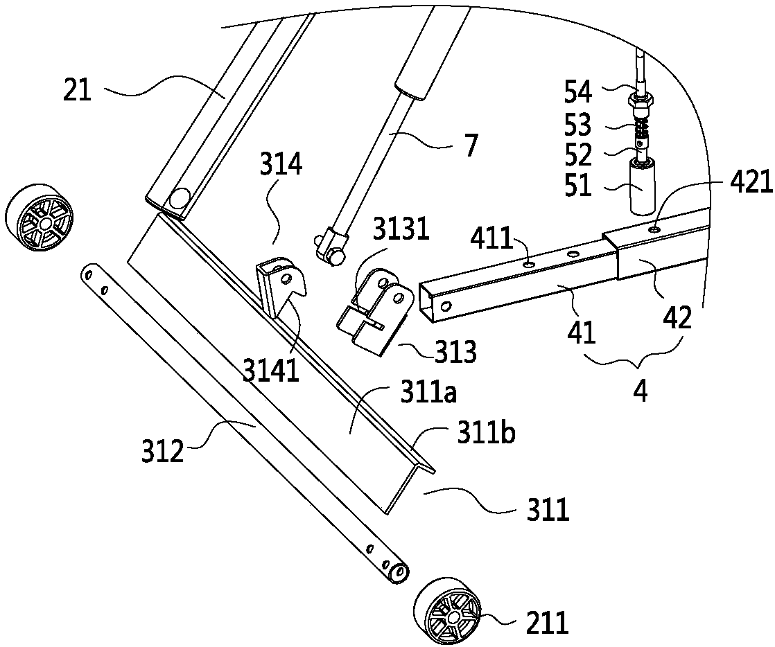
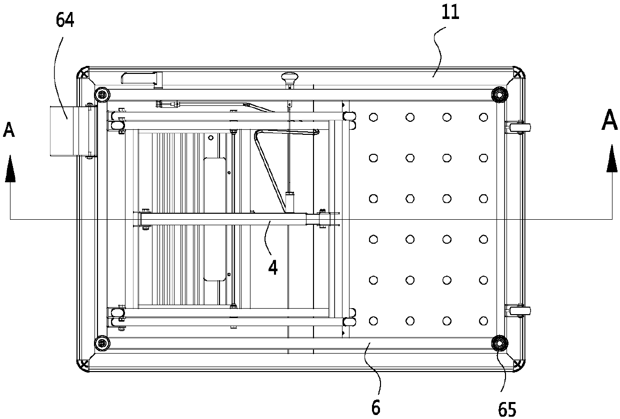
The invention discloses a lifting working platform, belonging to the field of lifting auxiliary equipment. Thelifting working platform comprises a working platform andtwo lifting fork frames for supporting the ascent and descent of the working platform, wherein a first connecting rod and a second connecting rod are connected between the two lifting fork frames, a retractable sleeve pipe is arranged between the first connecting rod and the second connecting rod, the telescopic sleeve pipe is correspondingly expanded and contracted when the working platform is raised and lowered, and the sleevepipe is provided with a locking device for multi-gear locking of the telescopic length of the sleeve pipe. The lifting working platform has the advantages that the lifting fork frames have their own locking function, the structure is simplified, and the manufacturing cost is reduced.

Description

【Technical field】 [0001] The invention relates to a lifting workbench, which belongs to the field of lifting auxiliary equipment. 【Background technique】 [0002] In some manufacturing enterprises, a series of manufacturing processes such as welding, grinding, drilling, etc. are usually encountered. Such manufacturing processes require a workbench to facilitate the placement of fixtures, processing equipment, etc., but in traditional enterprises This type of workbench is fixed. If the fixtures, processing equipment, and operator heights are different, it will often cause the operator to become very uncomfortable and inconvenient when actually operating. Seriously affect work efficiency. [0003] In view of this, workbenches that can be raised and lowered have also appeared on the existing market, but this type of elevating workbench can only be stagnated at the lowest position and the highest position, and can rarely hover in the middle position. Usually, driving devices su...

Claims


Application Information

Patent Timeline
Patent Type & Authority Applications(China)
IPC IPC(8): B66F7/06B66F7/28
CPCB66F7/065B66F7/28
Inventor 应征
Owner JINHUA ZHENFEI TOOLS
Learn More