
An air intake and exhaust device for a water supply steady flow tank

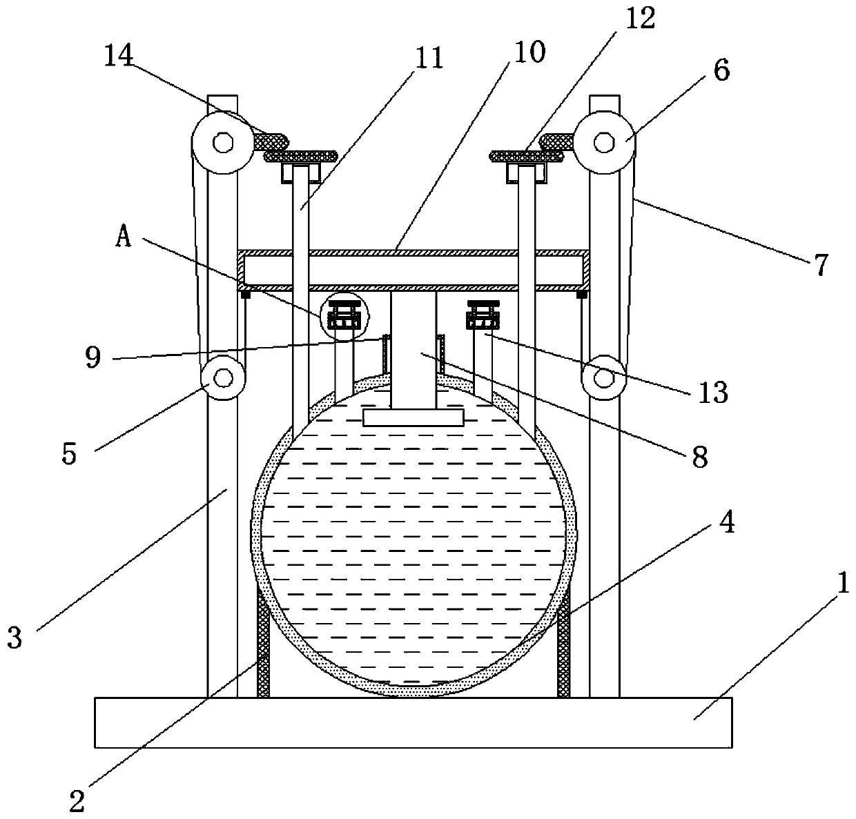
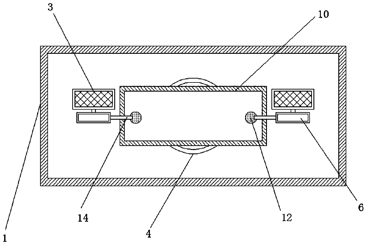
A technology of exhaust device and steady flow tank, which is applied in the direction of water supply device, water supply main pipeline, water supply pipeline system, etc., and can solve catastrophic, water-containing gas spraying out for a long distance, negative impact of the surrounding environment of water supply steady flow tank, etc. problem, to achieve the effect of improving safety

Active Publication Date: 2019-09-24
安徽亿洁环保科技有限公司
View PDF5 Cites 0 Cited by
  • Summary
  • Abstract
  • Description
  • Claims
  • Application Information

AI Technical Summary

Problems solved by technology

However, the traditional inlet and exhaust device of the water supply stabilizing tank directly discharges the gas in the water into the atmosphere around the inlet and exhaust device, which has a negative impact on the surrounding environment of the water supply stabilizing tank, especially when the pressure inside the tank is high or When the intake and exhaust device is faulty, the water-containing gas will be ejected far away, and if there is electrical equipment nearby, it may have disastrous consequences

Method used


Image

  • An air intake and exhaust device for a water supply steady flow tank
  • An air intake and exhaust device for a water supply steady flow tank
  • An air intake and exhaust device for a water supply steady flow tank

Examples


Embodiment Construction

[0016] The following will clearly and completely describe the technical solutions in the embodiments of the present invention with reference to the accompanying drawings in the embodiments of the present invention. Obviously, the described embodiments are only some, not all, embodiments of the present invention.

[0017] In describing the present invention, it should be understood that the terms "upper", "lower", "front", "rear", "left", "right", "top", "bottom", "inner", " The orientation or positional relationship indicated by "outside", etc. is based on the orientation or positional relationship shown in the drawings, and is only for the convenience of describing the present invention and simplifying the description, rather than indicating or implying that the referred device or element must have a specific orientation, so as to Specific orientation configurations and operations, therefore, are not to be construed as limitations on the invention.

[0018] refer to Figure ...


PUM


Abstract

The invention discloses a novel air inlet and exhaust device of a water supply flow-stabilizing tank. The novel air inlet and exhaust device comprises a base, wherein support rods fixedly connected with the base are symmetrically arranged on the upper side of the base, a first rotation groove and a second rotation groove are arranged in each support rod, a first rotation shaft rotatably connectedwith the first rotation groove is inserted in the first rotation groove, a second rotation shaft rotatably connected with the second rotation groove is inserted in the second rotation groove, the first rotation shaft is positioned below the second rotation shaft, and a first rotation plate is arranged on the first rotation shaft. The novel air inlet and exhaust device of the water supply flow-stabilizing tank has the advantages that through the combined action of air pressure in a tank body and the external atmospheric pressure, when air pressure in the tank body is relatively high, a connecting rope pulls a pressure block, then air can be exhausted from an air outlet pipe, meanwhile, the exhausted air passes through a drying device, thus moisture can be eliminated, therefore, the use safety of the device is improved, when air pressure in the tank body is relatively low, under the effect of the external atmospheric pressure, the air inlet pipe is opened, air enters the tank, and the air pressure in the tank is regulated.

Description

technical field [0001] The invention relates to the technical field of secondary water supply equipment, in particular to an air intake and exhaust device of a water supply steady flow tank. Background technique [0002] The steady flow tank is also called a negative pressure tank, which contains a negative pressure eliminator, etc. It is mainly used in the current high-rise water supply equipment. It is an indispensable part of the non-negative pressure water supply equipment. The system sets a constant pressure value. If the pipe network When the pressure is higher than the set pressure value, the pressure transmitter will feed back the pipe network pressure to the frequency conversion control cabinet, and the tap water can directly reach the user pipe network through the direct supply pipeline to supply water to the user. When the pressure of the municipal pipe network changes or the water consumption of the user pipe network changes so that the pipe pressure is lower tha...

Claims


Application Information

Patent Timeline
Patent Type & Authority Patents(China)
IPC IPC(8): E03B7/07
Inventor 胡毛虎
Owner 安徽亿洁环保科技有限公司
Learn More