
High-speed jet self-cleaning filtering device

A self-cleaning filtration, high-speed jet technology, applied in filtration separation, filtration treatment, fixed filter element filter, etc., can solve the problems of large pressure difference between inside and outside of the filter element, holding pressure, unable to completely clean the dirt, etc., to achieve safe operation, The effect of high degree of automation and strong self-cleaning ability

Pending Publication Date: 2018-02-09
康庆刚
View PDF0 Cites 1 Cited by
  • Summary
  • Abstract
  • Description
  • Claims
  • Application Information

AI Technical Summary

Problems solved by technology

However, there are generally two problems in the existing filters. One is that when the dirt holding capacity reaches a certain amount, the injection is stopped during cleaning, and the pressure in the well is used for reverse flushing. Because the liquid flow rate on the surface of the filter element is low, the surface of the filter element cannot be thoroughly cleaned. and dirt in the filter
The second is that in order to achieve a higher filtering effect, the specification of the filter element is micron, and mechanical impurities and scale are easy to remain on the filter channel of the filter element, which reduces the area of ​​the flow channel. The pressure difference between the inside and outside of the filter element is too large, and the pressure is suppressed. Although the filter currently used is equipped with a rotating handle arranged outside the filter housing to make the filter element move relative to the filter to achieve the purpose of descaling, it still requires the cooperation of manpower. , did not reach the level of automatic descaling in the unmanned state

Method used


Image

  • High-speed jet self-cleaning filtering device
  • High-speed jet self-cleaning filtering device
  • High-speed jet self-cleaning filtering device

Examples


Embodiment Construction

[0014] The present invention will be further described below in conjunction with specific embodiments, and the advantages and characteristics of the present invention will become clearer along with the description. However, these embodiments are only exemplary and do not constitute any limitation to the scope of the present invention. Those skilled in the art should understand that the details and forms of the technical solutions of the present invention can be modified or replaced without departing from the spirit and scope of the present invention, but these modifications and replacements all fall within the protection scope of the present invention.

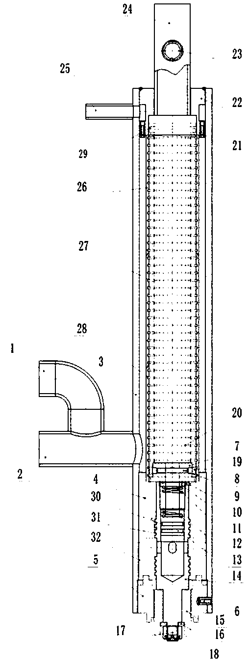
[0015] see Figure 1 to Figure 3 , the present invention relates to a high-speed jet self-cleaning filter device, comprising a housing 3, a liquid inlet connecting pipe 1, a sewage outlet connecting pipe 2 and a jet cleaning water inlet pipe 25, the housing 3 is arranged along the horizontal direction (for the convenience of i...


PUM


Abstract

The invention relates to a high-speed jet self-cleaning filtering device, which comprises a casing, a liquid inlet connecting pipe, a sewage discharging opening connecting pipe and a jet cleaning water inlet pipe, wherein the casing is arranged in the horizonal direction; the jet cleaning water inlet pipe is arranged at the lower side of the left end of the casing; the sewage discharging opening connecting pipe is arranged at the lower side of the right end of the casing; the liquid inlet connecting pipe is arranged at one side of the sewage discharging opening connecting pipe and is communicated with the sewage discharging opening connecting pipe; a jet device is welded at the left end of the casing; a copper spray nozzle is positioned inside the casing and is connected with the jet device through screw threads. The high-speed jet self-cleaning filtering device has the advantages that the self-cleaning capability is high; the operation is safe, simple and convenient; the automation degree is higher.

Description

technical field [0001] The invention relates to a filter device in the reinjection process of oil field sewage, in particular to a high-speed jet self-cleaning filter device. Background technique [0002] For oilfields developed by water flooding, in order to protect the environment and control costs, sewage reinjection after separation of produced fluid has become an important means of oilfield development. In order to ensure the qualified rate of sewage water quality, installing filters on the water injection pipeline is the key to ensuring water quality important method. However, there are generally two problems in the existing filters. One is that when the dirt holding capacity reaches a certain amount, the injection is stopped during cleaning, and the pressure in the well is used for reverse flushing. Because the liquid flow rate on the surface of the filter element is low, the surface of the filter element cannot be thoroughly cleaned. and dirt in the filter. The sec...

Claims


Application Information

Patent Timeline
IPC IPC(8): C02F1/00B01D29/58B01D29/64
CPCB01D29/58B01D29/6438C02F1/001C02F2103/10C02F2303/16
Inventor 康庆刚
Owner 康庆刚
Learn More