
Grinder

A technology of grinder and grinding surface, which is applied in the field of grinder, which can solve the problems that the grinder cannot grind, stay away from the grinding surface, grind, etc., and achieve the effect of solving grinding problems and good grinding efficiency

Pending Publication Date: 2018-02-09
伍尚强
View PDF2 Cites 2 Cited by
  • Summary
  • Abstract
  • Description
  • Claims
  • Application Information

AI Technical Summary

Problems solved by technology

[0002] At present, the grinder used to grind general materials relies on the weight of the material itself to continuously enter the grinding surface to achieve the effect of grinding and crushing. However, when it is used to grind oily materials, after grinding for a period of time, the oily materials being ground will become viscous and stick to the surface. At the same time, the bonded material may accumulate outside the grinding surface, so that the grinder cannot continue to grind the material
[0003] Although the grinder disclosed in WO2015138972 has a mechanism that can move axially, the mechanism is far away from the grinding surface and cannot solve the above problems
Another example is in the patent of CN201110339395.4, although the disclosed grinder has a spiral push rod, when the oily materials are bonded together and the screw space is blocked, the grinder cannot continue to grind the material

Method used


Image

  • Grinder
  • Grinder
  • Grinder

Examples


Embodiment Construction

[0034] A number of implementations of the present application will be disclosed in the following figures. For the sake of clarity, many practical details will be described together in the following description. It should be understood, however, that these practical details should not be used to limit the application. That is to say, in some embodiments of the present application, these practical details are unnecessary. In addition, for the sake of simplifying the drawings, some well-known and commonly used structures and components will be shown in a simple schematic manner in the drawings.

[0035] The terms "first", "second", etc. used herein do not refer to the order or order, nor are they used to limit the present application, but are only used to distinguish components or operations described with the same technical terms. .

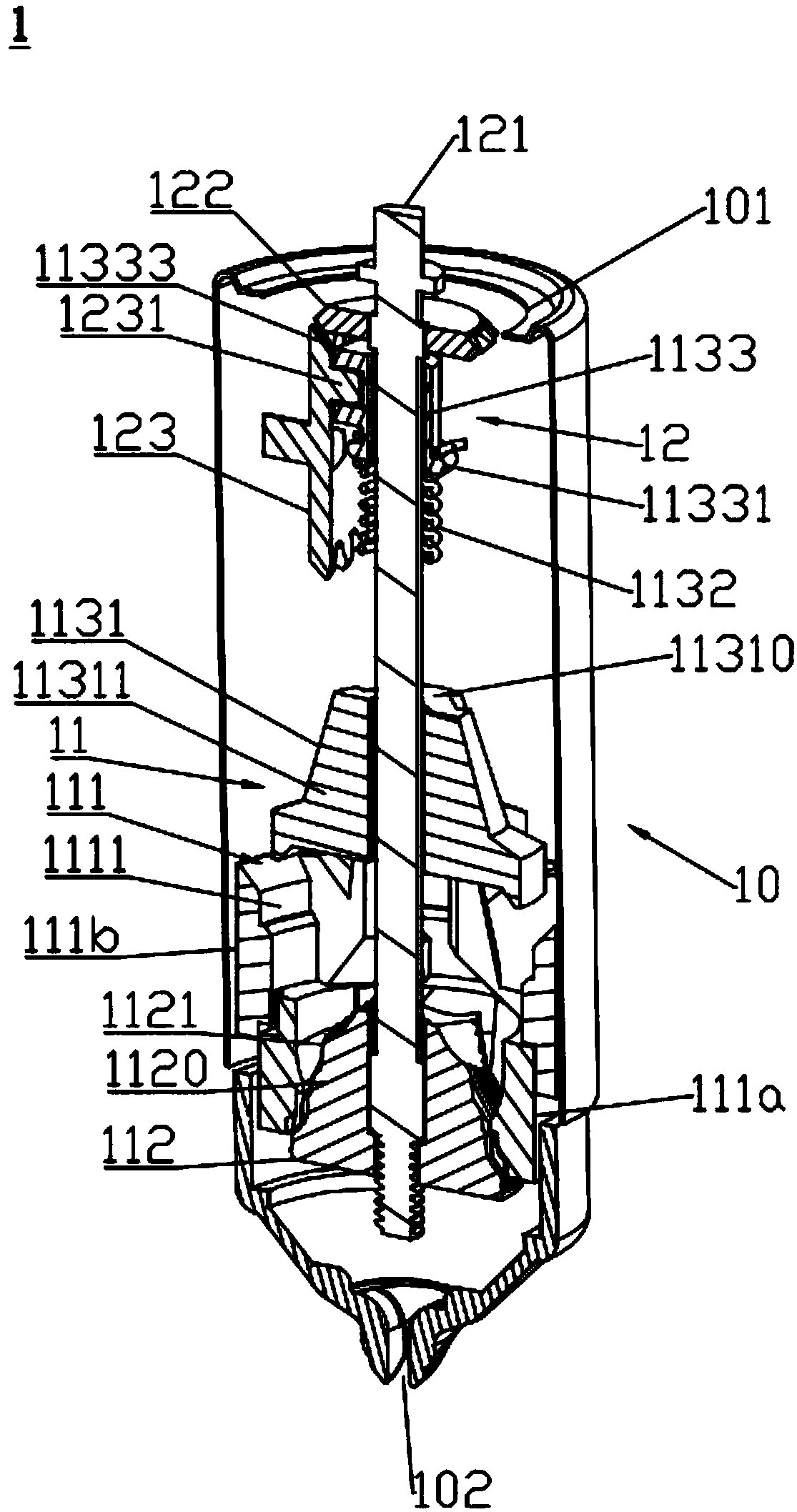
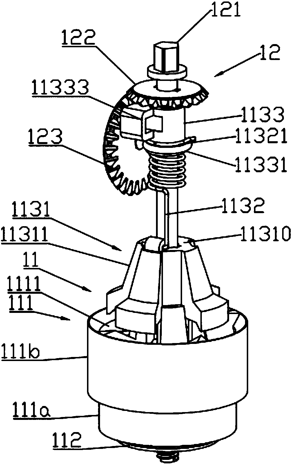
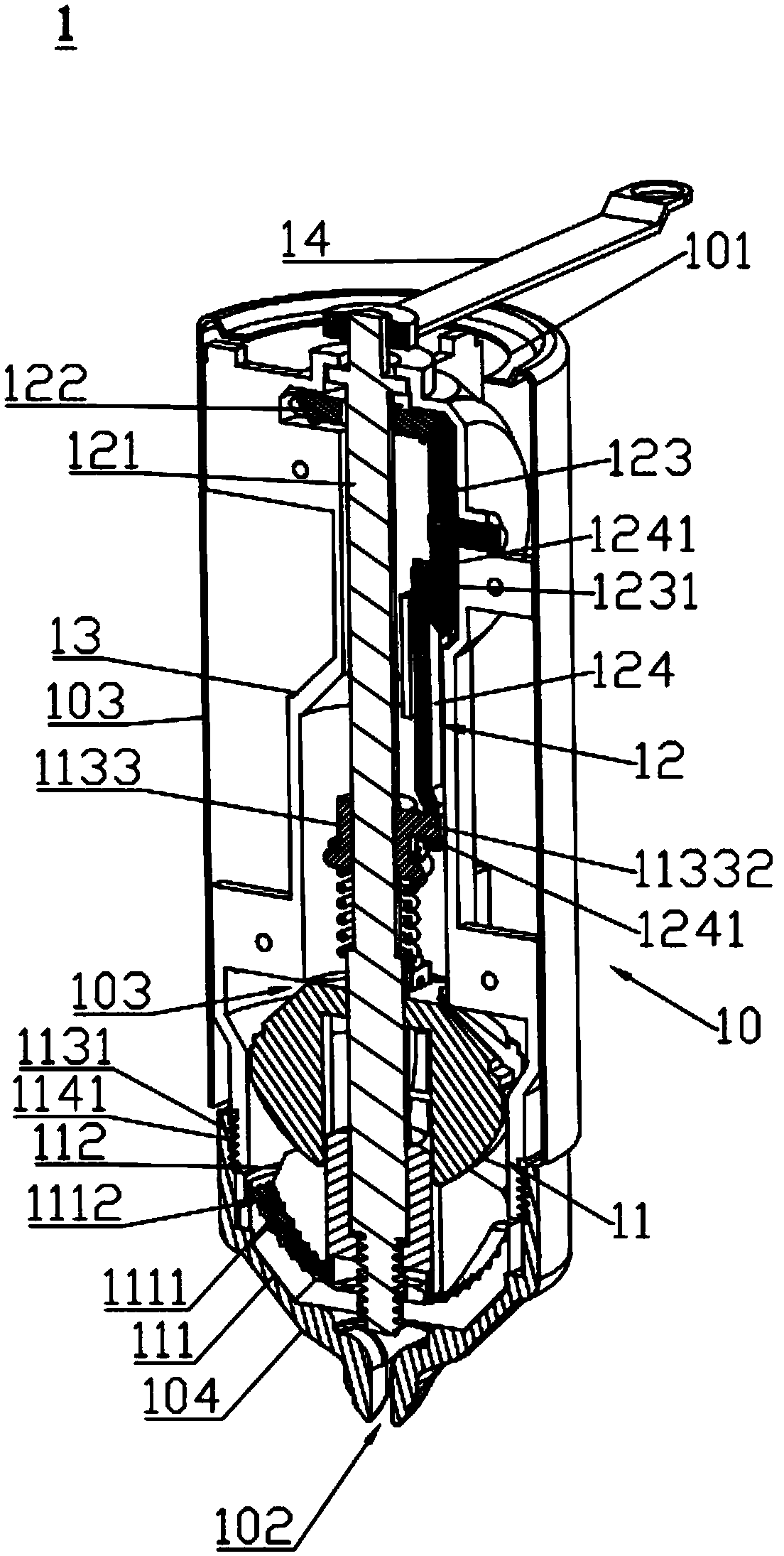
[0036] see figure 1 and figure 2 , which is a perspective view of the grinder 1 and a perspective view of the grinding mechanism 11 and the d...


PUM


Abstract

The invention relates to a grinder. The grinder comprises a grinding mechanism and a driving mechanism which drives the grinding mechanism; the grinding mechanism comprises a first grinding core, a second grinding core and a material pushing structure, the driving mechanism is connected with the first grinding core, the second grinding core and the material pushing structure, and the grinding surface of the first grinding core and the grinding surface of the second grinding core relatively rotate and drive the material pushing structure to move vertically. According to the grinder, the material pushing structure vertically moves to be near the grinding surface of the dynamic grinding core or the grinding surface of the static grinding core and constantly pushes materials to the portion between the grinding surface of the dynamic grinding core and the grinding surface of the static grinding core, and the dynamic grinding core and the static grinding core relatively rotate to grind the materials between the dynamic grinding core and the static grinding core, so that the purpose of grinding the oil materials is effectively achieved; moreover, the grinder has good grinding efficiency.

Description

technical field [0001] The invention relates to the technical field of material grinding, in particular to a grinder. Background technique [0002] At present, the grinder used to grind general materials relies on the weight of the material itself to continuously enter the grinding surface to achieve the effect of grinding and crushing. However, when it is used to grind oily materials, after grinding for a period of time, the oily materials being ground will become viscous and stick to the surface. At the same time, the bonded material may accumulate outside the grinding surface, so that the grinder cannot continue to grind the material. [0003] Although the grinder disclosed in WO2015138972 has a mechanism capable of axial movement, the mechanism is far away from the grinding surface and cannot solve the above problems. Another example is in the patent of CN201110339395.4, although the disclosed grinder has a spiral push rod, when the oily materials are bonded together an...

Claims


Application Information

Patent Timeline
Patent Type & Authority Applications(China)
IPC IPC(8): A47J42/06A47J42/08
CPCA47J42/06A47J42/08B02C19/00
Inventor 伍尚强
Owner 伍尚强
Learn More