Rotary individual bee sampling mechanism
A rotary, honeybee technology, applied to the device, application, animal husbandry and other directions of catching or killing insects, it can solve the problems of bee escape, complex structure, etc., and achieve the effect of simple operation and simple structure
- Summary
- Abstract
- Description
- Claims
- Application Information
AI Technical Summary
Problems solved by technology
Method used
Image
Examples
Embodiment 1
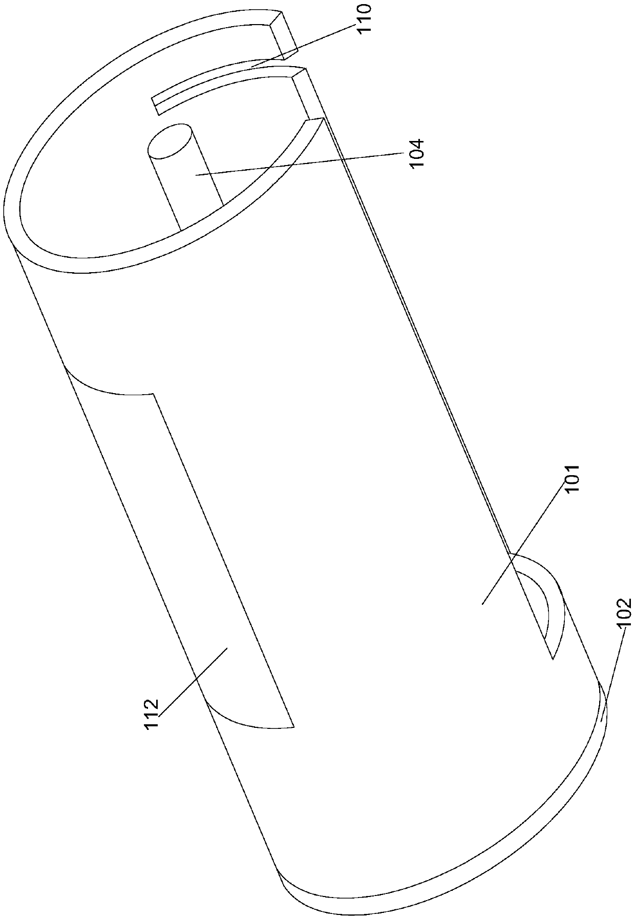
[0023] In this embodiment, in order to facilitate the removal of the inner tube when needed, preferably, the length of the inner tube 106 is shorter than the length of the cylinder 101, and the end of the inner tube 106 close to the base 102 A sleeve 107 is arranged in the middle of the seal cover 105, the seal cover 105 is rotatably connected to the outer wall of the sleeve 107 through a bearing, and a spring 109 is arranged between the sleeve 107 and the base 102 When the inner tube 106 is located inside the barrel 101 , the spring 109 is pressed by the sleeve 107 to be in a compressed state. During processing, the sleeve can slide axially relative to the rotating shaft. After the sleeve is set on the rotating shaft, the sleeve is moved toward the base along the axial direction of the rotating shaft. At this time, the sealing cover fixed on the inner tube and the sleeve pass through. Bearing connection, so that the sealing cover can drive the inner tube and the sleeve to mov...
Embodiment 2
[0027] In order to fix the inner tube conveniently, in this embodiment, preferably, a pin 108 is provided on the sealing cover 105 at the end of the inner tube 106 away from the base 102, and the inner tube 106 is located at the The plug pin 108 can be inserted into the cylinder 101 inside the cylinder 101 . During processing, a through hole can be provided on the cylinder, and the pin can be inserted through the through hole, so that the pin can be pressed against the outside of the sealing cover at the end away from the base. The specific position and quantity of the pin can be determined according to the position of the cylinder and the sealing cover. Sure.
[0028] Further preferably, in this embodiment, a slot 110 is provided at the end of the cylinder 101 away from its base 102, the slot 110 is arranged along the circumference of the side wall of the cylinder 101, and the inner When the tube 106 rotates around the rotating shaft 104 , the pin 108 can be embedded in the ...
Embodiment 3
[0030] In order to avoid death of bees due to lack of oxygen, in this embodiment, preferably, a through hole is provided on the side wall of the inner tube 106, and a breathable mesh 111 is provided on the through hole. After the bees are closed inside the inner tube, the inside of the inner tube can be ventilated from the side through the breathable mesh. The installation position and installation quantity of the ventilation net can be determined according to the size of the inner pipe.
[0031] In order to facilitate the observation of the conditions of the bees in the tube, further preferably, in this embodiment, a long observation hole 112 is provided on the side wall of the cylinder 101, and a transparent Glass. The size and position of the transparent glass can be determined according to the size of the cylinder.
[0032] When installing, when the inner tube is fixed in the cylinder, the observation hole corresponds to the opening position on the inner tube, so that it...
PUM
 Abstract
Description
Claims
Application Information
 - R&D Engineer
- R&D Manager
- IP Professional
- Industry Leading Data Capabilities
- Powerful AI technology
- Patent DNA Extraction
Browse by: Latest US Patents, China's latest patents, Technical Efficacy Thesaurus, Application Domain, Technology Topic, Popular Technical Reports.
© 2024 PatSnap. All rights reserved.Legal|Privacy policy|Modern Slavery Act Transparency Statement|Sitemap|About US| Contact US: help@patsnap.com


