Socket with switch
A socket and switch technology, which is applied to the parts of the connection device, fixed/insulated contact members, electrical components, etc., can solve the problem that sockets with switches cannot be switched between scenes, etc., to achieve convenient scene switching, simple and convenient operation, and reduced The effect of small safety hazards
- Summary
- Abstract
- Description
- Claims
- Application Information
AI Technical Summary
Problems solved by technology
Method used
Image
Examples
Embodiment 1
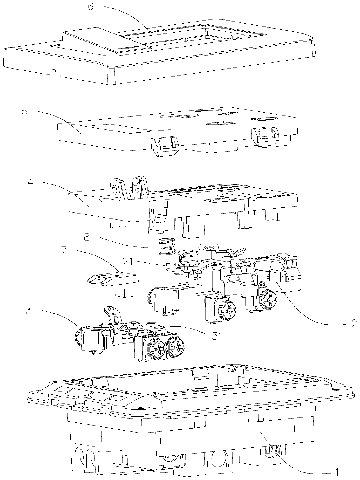
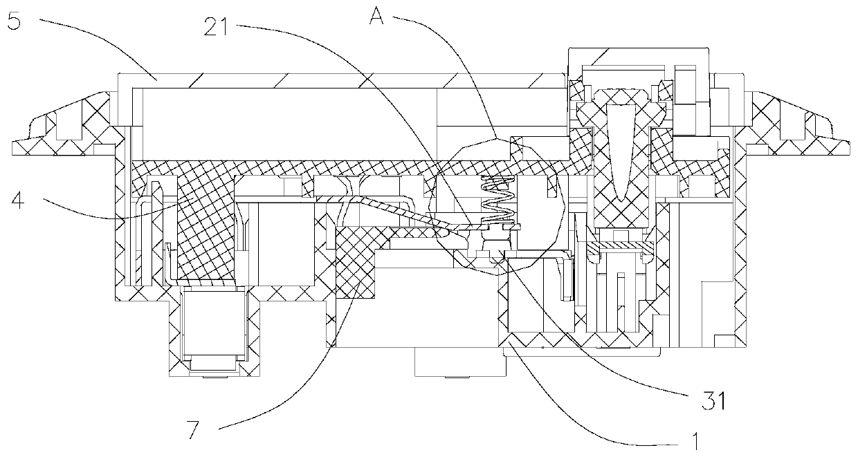
[0038] Such as figure 1 , figure 2 As shown, the embodiment of the present invention provides a socket with a switch, including: a rear seat 1; a socket terminal assembly 2 and a switch terminal assembly 3 installed in the rear seat 1; The pressure plate assembly 4 above the switch terminal assembly 3; the face cover 5 and the panel assembly 6 installed above the pressure plate assembly 4. The face cover 5 is mounted on the rear seat 1 by screwing or fastening, and the panel assembly 6 is mounted on the rear seat 1 by fastening.
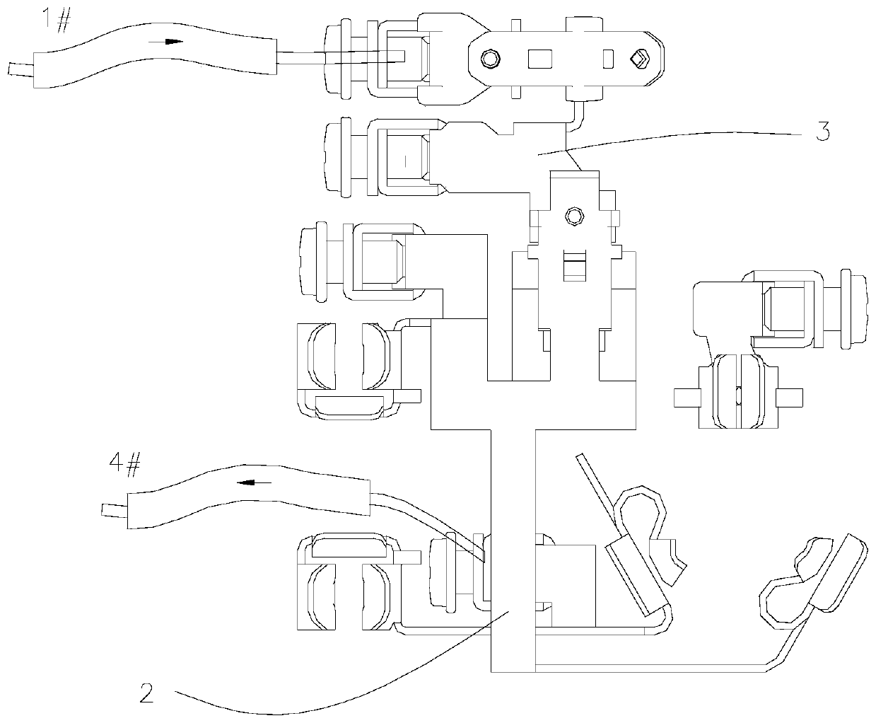
[0039] The socket terminal assembly 2 is provided with a first contact piece 21, and the switch terminal assembly 3 is provided with a second contact piece 31, and the first contact piece 21 and the second contact piece 31 can elastically contact;
[0040] A slidable barrier 7 is also provided between the first contact piece 21 and the second contact piece 31 , and the barrier 7 can separate the first contact piece 21 from the second contact piece...
Embodiment 2
[0044] Such as Figure 7 , Figure 8 As shown, in an optional embodiment of the present invention, the rear seat 1 is provided with a sliding slot 11 , and the barrier member 7 is slidably installed in the sliding slot 11 . The chute 11 is a structure with a plane at the bottom. The chute 11 is provided so that the barrier member 7 can slide smoothly on the bottom plane of the chute 11, thereby facilitating the user to switch the usage scenarios of the socket.
[0045]In order to prevent the barrier member 7 from falling out of the sliding groove 11 , in an optional embodiment of the present invention, first limiting portions 12 are provided on both side walls of the sliding groove 11 . The first limiting part 12 is a protrusion arranged on the two side walls, and there is a small gap between the protrusion and the barrier 7 , so that the barrier 7 can slide smoothly on the bottom plane of the slide groove 11 .
[0046] Furthermore, a first guide surface 121 is provided abov...
Embodiment 3
[0048] Such as Figure 9 As shown, in an optional embodiment of the present invention, the barrier member 7 includes two sliders 71, a lever 72 connected to the two sliders 71 and a barrier sheet arranged between the two sliders 71 73, the middle part of the chute 11 is provided with an escape groove 13 for the sliding of the driving rod 72. The height of the sliding block 71 is slightly smaller than the distance between the first limiting portion 12 and the bottom plane of the chute 11 , so that the blocking member 7 can slide smoothly on the bottom plane of the chute 11 . The lever 72 provides a force application part for the user when sliding the blocking element 7, so that the user can slide the blocking element 7 to a desired position. The thickness of the blocking sheet 73 is set thinner, when the blocking sheet 73 is inserted between the first contact sheet 21 and the second contact sheet 31, the elastic deformation of the first contact sheet 21 and the second contact ...
PUM
 Abstract
Description
Claims
Application Information
 - R&D Engineer
- R&D Manager
- IP Professional
- Industry Leading Data Capabilities
- Powerful AI technology
- Patent DNA Extraction
Browse by: Latest US Patents, China's latest patents, Technical Efficacy Thesaurus, Application Domain, Technology Topic, Popular Technical Reports.
© 2024 PatSnap. All rights reserved.Legal|Privacy policy|Modern Slavery Act Transparency Statement|Sitemap|About US| Contact US: help@patsnap.com


