Method, Structure and Restoration System of Image Compensation Signal Generation

A signal generation and image compensation technology, applied in image enhancement, image analysis, image data processing and other directions, can solve the problems of low gray level adverse effects, inability to obtain compensation effects, etc., and achieve accurate compensation effects.

Active Publication Date: 2020-05-08
HKC CORP LTD +1
View PDF10 Cites 0 Cited by
  • Summary
  • Abstract
  • Description
  • Claims
  • Application Information

AI Technical Summary

Problems solved by technology

Then the disadvantages of this current approach can also be imagined. If there is a display device with uneven light source (Mura) that can only be seen from 30% grayscale, then using this linear operation will not only fail to obtain a good compensation effect, but will It will adversely affect the low grayscale where the light source unevenness (Mura) cannot be seen originally.

Method used

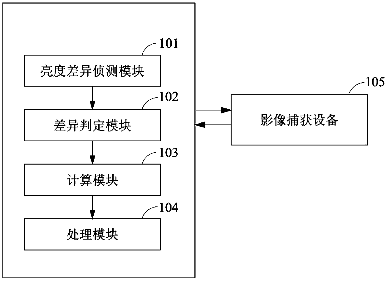
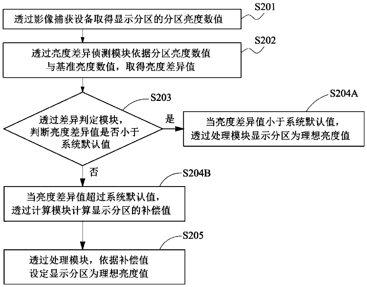
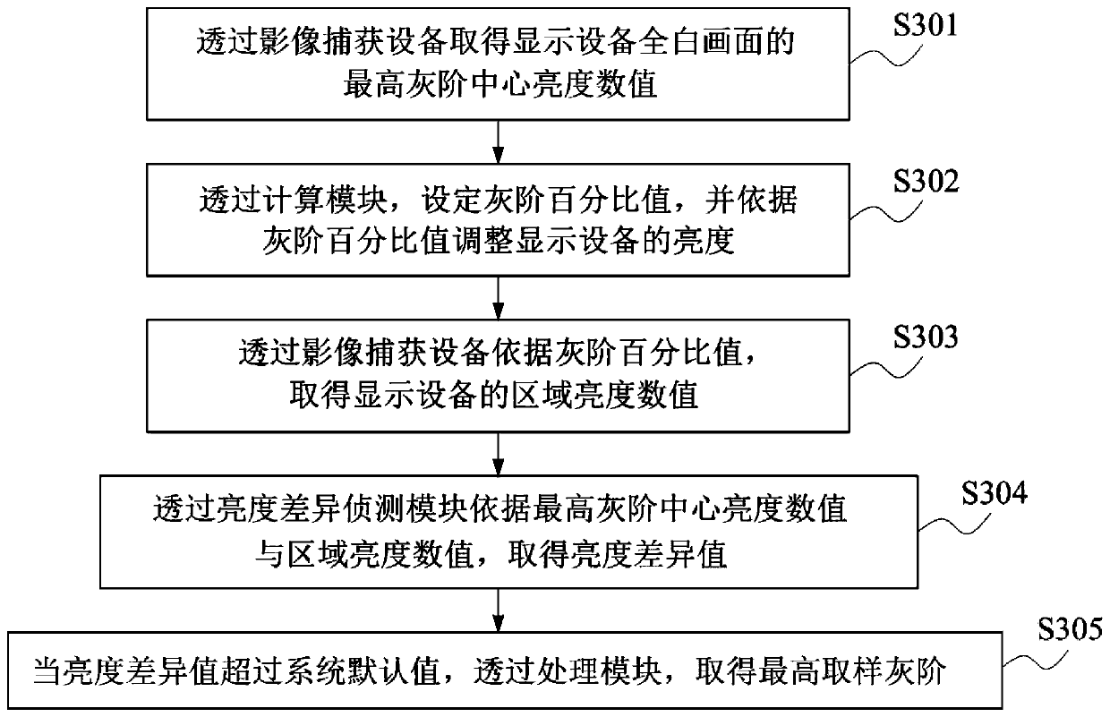

Image

  • Method, Structure and Restoration System of Image Compensation Signal Generation
  • Method, Structure and Restoration System of Image Compensation Signal Generation
  • Method, Structure and Restoration System of Image Compensation Signal Generation

Examples


Embodiment Construction

[0028] The description of the following embodiments refers to the attached drawings to illustrate specific embodiments that can be implemented in this application. The direction terms mentioned in this application, such as "up", "down", "front", "rear", "left", "right", "inner", "outer", "side", etc., are for reference only The direction of the additional schema. Therefore, the directional terms used are used to illustrate and understand the application, rather than to limit the application.

[0029] The drawings and descriptions are to be regarded as illustrative in nature and not restrictive. In the figures, units with similar structures are indicated by the same reference numerals. In addition, for understanding and ease of description, the size and thickness of each component shown in the drawings are arbitrarily shown, but the application is not limited thereto.

[0030] In addition, in the specification, unless expressly described to the contrary, the word "comprising" wil...


PUM


Abstract

A method for generating an image compensation signal, a structure and a repair system (701): obtaining a central brightness value (S301, S401) of a display device (600) by means of an image capture device (105, 702); then setting a grayscale percentage value by means of a calculation module (103), and adjusting the brightness (S302, S402) of the display device (600) according to the grayscale percentage value; obtaining a brightness value (S303, S403) of the display device (600) by means of the image capture device (105, 702) according to the grayscale percentage value; obtaining a brightness difference value (S304, S404) by means of a brightness difference detecting module (101); and determining, by means of a difference determination module (102), whether the brightness difference value is smaller than a system default value; when the brightness difference value is smaller than the system default value, reducing the grayscale percentage value by means of the calculation module (103), and then comparing again; if the brightness difference value exceeds the system default value, obtaining a sample grayscale by means of a processing module (104).

Description

Technical field [0001] The present invention relates to the field of display, in particular to a method, structure and repair system for generating an image compensation signal. Background technique [0002] With the rapid development of the display technology industry, liquid crystal displays have become mainstream products in recent years. Driven by user demand and industry competition pressure, liquid crystal displays have the advantages of high resolution, high brightness, and no geometric distortion. At the same time, due to their small size, light weight and low power consumption, they are widely used in people’s daily use. In consumer electronics products, such as TVs, computers, mobile phones, tablets, etc. The flat display module is the main component of the liquid crystal display. Its manufacturing process is complicated and requires nearly a hundred processes. Therefore, various display defects will inevitably occur in the manufacturing process. These display defects ...

Claims


Application Information

Patent Timeline
Patent Type & Authority Patents(China)
IPC IPC(8): G09G3/20G06T5/00G06T7/90
CPCG06T5/00G06T7/90G09G3/2007G09G2320/0626
Inventor 邱彬
Owner HKC CORP LTD
Why Eureka
Try Eureka