Optimizing method and optimizing equipment of brightness compensation

A brightness compensation and brightness technology, applied in static indicators, instruments, etc., to solve problems such as affecting the final effect of Demura, the position to be compensated cannot be eliminated, and the precise control of the gamma curve.

Active Publication Date: 2019-12-31
HKC CORP LTD +1
View PDF10 Cites 0 Cited by
  • Summary
  • Abstract
  • Description
  • Claims
  • Application Information

AI Technical Summary

Problems solved by technology

[0007] At present, this method is relatively simple and easy, but the premise of calculating the brightness compensation data is to assume that the panel to be compensated is already a standard Gamma2. To be accurately controlled, and the center point to be compensated (mura) generally cannot be eliminated, so it will be easier to affect the final effect of Demura
[0008] At the same time, by default, the calculation will be performed for each area, and in order to ensure the Demura effect, the minimum unit of the area to be compensated should not be too large (generally 8*8 pixel units), so the final brightness compensation data of the entire panel to be compensated The amount will be larger, so the capacity of the external memory (Demura flash) will be larger, and the internal RAM of the processing IC on the driver board will also be larger, which will also bring limitations on data transmission time and rate.

Method used


Image

  • Optimizing method and optimizing equipment of brightness compensation
  • Optimizing method and optimizing equipment of brightness compensation
  • Optimizing method and optimizing equipment of brightness compensation

Examples


Embodiment Construction

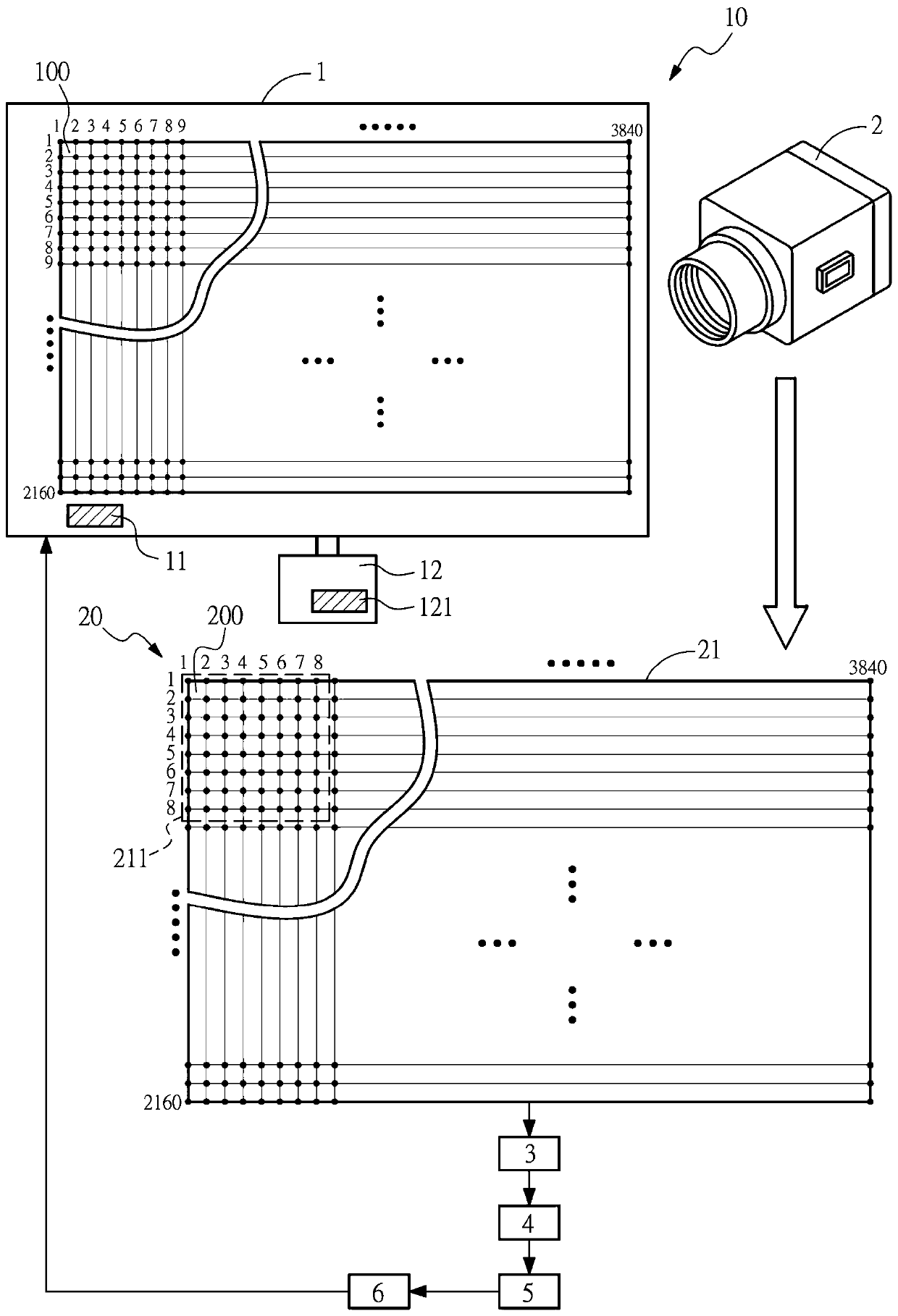
[0055] The following descriptions of the various embodiments refer to the accompanying drawings to illustrate specific embodiments in which the present invention can be practiced. The directional terms mentioned in the present invention, such as "up", "down", "front", "back", "left", "right", "inside", "outside", "side", etc., are for reference only The orientation of the attached schema. Therefore, the directional terms used are used to illustrate and understand the present invention, but not to limit the present invention.

[0056] The drawings and descriptions are to be regarded as illustrative in nature and not restrictive. In the figures, structurally similar units are denoted by the same reference numerals. In addition, the size and thickness of each component shown in the drawings are arbitrarily shown for understanding and ease of description, but the present invention is not limited thereto.

[0057] In the drawings, the thickness of layers, films, panels, regions,...


PUM


Abstract

Provided are a method for optimizing brightness compensation, and a pre-processing apparatus. The method comprises: providing a brightness acquisition device; capturing an image of a panel (1) to undergo compensation as a brightness compensation reference image (21), the panel (1) having multiple first pixel units (100), the brightness acquisition device having multiple second pixel units (200), the brightness compensation reference image (21) consisting of multiple photographing units (211), the photographing unit (211) consisting of multiple second pixel units (200), wherein a side length of the second pixel unit (200) is larger than a side length of the first pixel unit (100); taking four second pixel units (200) at four end points of the photographing units (211) as brightness references, and obtaining, by means of a specific operation, multiple brightness compensation data items for the remaining second pixel units (200) in the photographing units (211); and using the brightness compensation data items to perform brightness compensation on the first pixel units (100) corresponding to the respective photographing units (211).

Description

technical field [0001] The invention relates to an optimization method and optimization equipment for brightness compensation, in particular to an optimization method and optimization equipment for achieving brightness compensation by changing the resolution of a camera. Background technique [0002] Flat-panel display devices have many advantages such as thin body, power saving, and no radiation, and have been widely used. Existing flat panel display devices mainly include liquid crystal display devices (Liquid Crystal Display, LCD) and organic light emitting diode display devices (Organic Light Emitting Display, OLED). Organic light-emitting diode display devices have excellent characteristics such as self-illumination, no need for backlight, high contrast, thin thickness, wide viewing angle, fast response speed, can be used for flexible panels, wide operating temperature range, and relatively simple structure and manufacturing process. It is considered as an emerging app...

Claims


Application Information

Patent Timeline
Patent Type & Authority Patents(China)
IPC IPC(8): G09G3/3208
CPCG09G3/3208G09G2320/0233
Inventor 王明良
Owner HKC CORP LTD
Why Eureka
Try Eureka