
A Sparse Method for Loop Antenna Arrays Based on Quantum Chicken Flock Evolution Mechanism

A loop antenna, quantum technology, applied in quantum computers, constraint-based CAD, design optimization/simulation, etc., can solve problems such as variation, high side lobes in the pattern, and achieve reduced failure rate, fast convergence speed, and easy improvement. The effect of being stuck in a local optimum

Active Publication Date: 2021-01-05
HARBIN ENG UNIV
View PDF4 Cites 0 Cited by
  • Summary
  • Abstract
  • Description
  • Claims
  • Application Information

AI Technical Summary

Problems solved by technology

However, the periodic thinning of antenna elements will cause very high side lobes in the pattern. After sparseness, the effect of the antenna array pattern will be much worse than when it is full.

Method used


Image

  • A Sparse Method for Loop Antenna Arrays Based on Quantum Chicken Flock Evolution Mechanism
  • A Sparse Method for Loop Antenna Arrays Based on Quantum Chicken Flock Evolution Mechanism
  • A Sparse Method for Loop Antenna Arrays Based on Quantum Chicken Flock Evolution Mechanism

Examples


Embodiment Construction

[0049]The following examples describe the present invention in more detail.

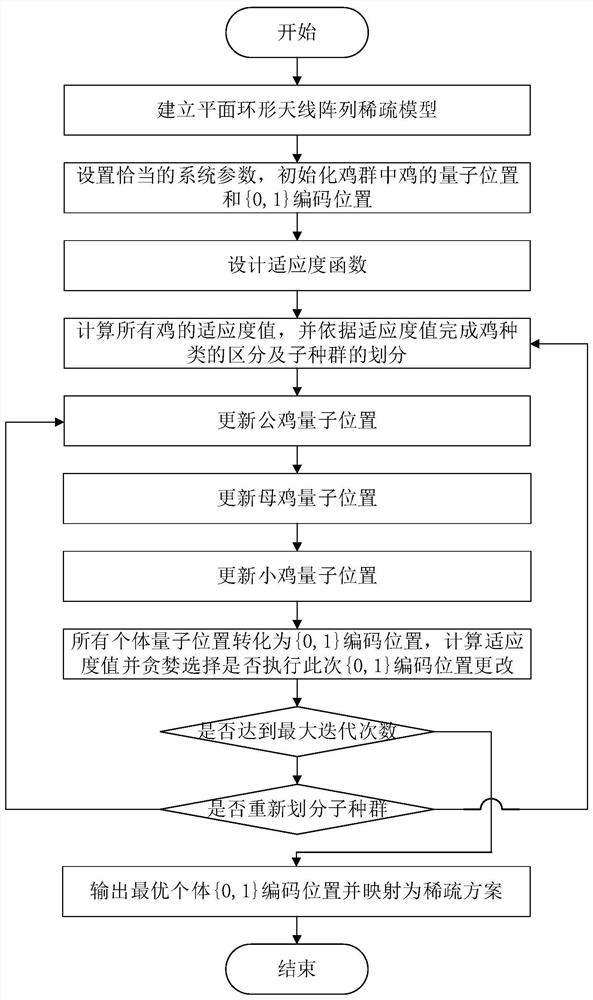
[0050]Such asfigure 1 As shown in the process, the steps of the loop antenna array sparse method based on the quantum chicken evolution mechanism of the present invention are as follows:

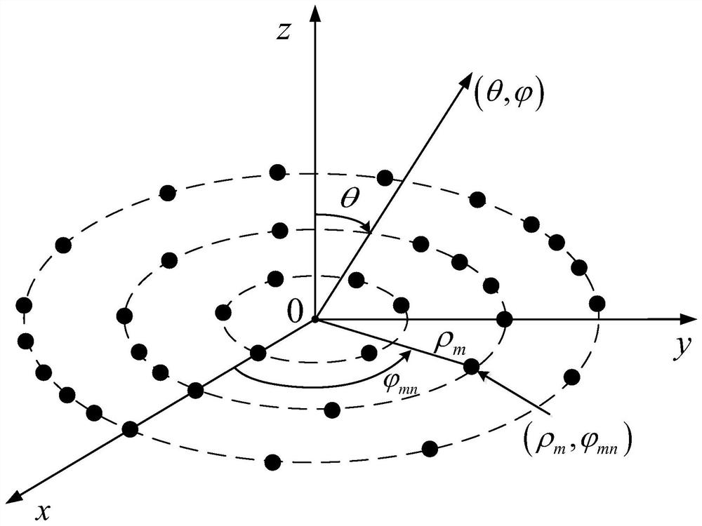
[0051]Step 1: Establish a sparse model of the loop antenna array. For a uniform single ring array with the center of the circle as the origin of the coordinates and the radius of a in the xoy plane, the rotation angle between the line of the nth element and the origin of the coordinates and the x axis isIts location coordinates areThe position vector isAssuming that the distance from the origin of the coordinates to an observation point in the far area is r, the unit vector in this direction isThe distance from the nth element to the observation point is Rn, Then the far-field radiation field strength of the array element is:

[0052]

[0053]Where C is a constant, j is an imaginary unit, k=2πa / λ is the wave number,Is the array elem...


PUM


Abstract

The invention provides an annular antenna array sparse method based on a quantum chicken evolution mechanism. The method comprises the following steps that: 1: establishing an annular antenna array sparse model; 2: setting an initial parameter; 3: designing a fitness function; 4: calculating the fitness value of each chick in a population, distinguishing the category of the chicken, and dividing sub-populations; 5, 6, and 7: independently constructing the quantum vector rotation angle update formula of roosters, hens and chicken, updating the quantum vector rotation angle, and updating a quantum position; 8: through a measurement way, converting into a [0,1] coding position, calculating the fitness value of the [0,1] coding position, and updating the individual historical optimal solutionand the global optimal solution of each chick; and 9: judging whether a maximum iteration is achieved or not. The method is higher in rate of convergence and higher in accuracy of convergence, and hasa good spare effect on solving the problem of annular antenna array sparse construction, the complexity and the cost of antenna array system are greatly lowered, and an expectant requirement is achieved.

Description

Technical field[0001]The invention relates to a sparse method for smart array antennas, in particular to a sparse method for loop antenna arrays.Background technique[0002]With the rapid development of science and technology in recent years, the requirements for antenna technology in various fields are also increasing. In order to enable antennas to meet the needs brought by the rapid development of technology, antenna technology has rapidly risen and developed, and many new antennas have emerged, including antenna arrays. The antenna array is to place many antenna elements in a certain arrangement so that their radiation field vectors are superimposed to obtain the total radiation field to meet the high gain and high directivity requirements in practical applications. The excellent effect of the huge antenna array makes the antenna array an indispensable part of some projects.[0003]In some radar and satellite antenna systems, the antenna array is composed of thousands or even tens o...

Claims


Application Information

Patent Timeline
Patent Type & Authority Patents(China)
IPC IPC(8): G06F30/27G06F30/18G06N10/00G06N3/00G06F111/04
CPCG06N3/006G06F30/18G06F30/20
Inventor 高洪元张晓桐侯阳阳刁鸣张世铂池鹏飞刘子奇苏雨萌王宇
Owner HARBIN ENG UNIV
Learn More