
Single column type offshore wind driven generator foundation structure

A technology for wind power generators and basic structures, applied in basic structure engineering, construction, etc., can solve the problems of increased construction and towing difficulty, great influence, large engineering volume, etc., to solve the problem of limited application range of water depth and light structure design , Good water depth applicability

Pending Publication Date: 2018-02-02
SHANGHAI INVESTIGATION DESIGN & RES INST
View PDF5 Cites 1 Cited by
  • Summary
  • Abstract
  • Description
  • Claims
  • Application Information

AI Technical Summary

Problems solved by technology

For shallow water areas, fixed foundations are generally used. Fixed foundations are greatly affected by seabed geological conditions and water depth conditions, and the amount of engineering is large and the construction process is relatively complicated.
For deep-sea areas, floating foundations are generally used. Floating foundations include single-column foundations, semi-submersible foundations, and tension-leg foundations; semi-submersible foundations are large in size, which increases the difficulty of construction and towing; Tendon performance requirements are high, and high-frequency vibration is likely to cause fatigue damage; the single-column foundation is generally a huge upright cylinder, which relies on buoyancy to support equipment on the water surface, and its stability comes from the fact that the center of gravity is lower than the center of buoyancy. And it is fixed by chain anchor cable, but the single-column foundation requires deeper water depth

Method used


Image

  • Single column type offshore wind driven generator foundation structure

Examples


Embodiment Construction

[0033] The implementation of the present invention will be illustrated by specific specific examples below, and those skilled in the art can easily understand other advantages and effects of the present invention from the contents disclosed in this specification.

[0034] Please refer to attached picture. It should be noted that the structures, proportions, sizes, etc. shown in the drawings attached to this specification are only used to match the content disclosed in the specification, for those who are familiar with this technology to understand and read, and are not used to limit the implementation of the present invention. Limiting conditions, so there is no technical substantive meaning, any modification of structure, change of proportional relationship or adjustment of size, without affecting the effect and purpose of the present invention, should still fall within the scope of the present invention. The disclosed technical content must be within the scope covered. At t...


PUM


Abstract

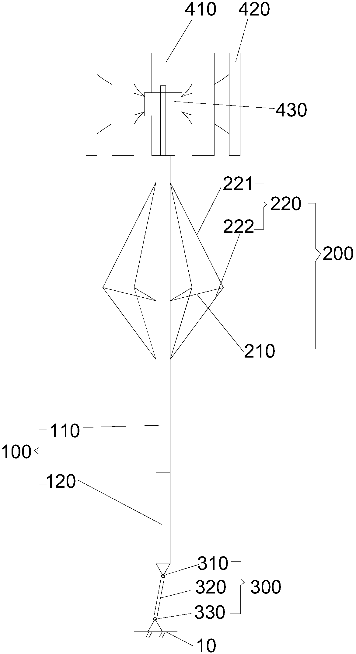
The invention provides a single column type offshore wind driven generator foundation structure. The single column type offshore wind driven generator foundation structure comprises a foundation column body and multiple suspension cable assemblies arranged on the peripheral face of the foundation column body. All the suspension cable assemblies are evenly arranged in the circumferential directionof the peripheral face of the foundation column body. Each suspension cable assembly comprises a suspension cable supporting frame and a suspension cable part. The upper ends and the lower ends of thesuspension cable parts are connected with the peripheral face of the foundation column body. One end of each suspension cable supporting frame is connected with the foundation column body, and the other end of each suspension cable supporting frame is connected with the corresponding suspension cable part to support the suspension cable part. Each suspension cable part is divided by the corresponding suspension cable supporting frame into an upper inclined cable portion and a lower inclined cable portion. The single column type offshore wind driven generator foundation structure is light in structural design, the bending moment of the foundation column body can be effectively reduced, and the foundation work amount is small.

Description

technical field [0001] The invention relates to the technical field of marine engineering, in particular to a single-column offshore wind power generator basic structure. Background technique [0002] Offshore wind turbine foundations are divided into two types: fixed foundations and floating foundations. For shallow water areas, fixed foundations are generally used. Fixed foundations are greatly affected by seabed geological conditions and water depth conditions, and the engineering volume is large and the construction process is relatively complicated. For deep-sea areas, floating foundations are generally used. Floating foundations include single-column foundations, semi-submersible foundations, and tension-leg foundations; semi-submersible foundations are large in size, which increases the difficulty of construction and towing; Tendon performance requirements are high, and high-frequency vibration is likely to cause fatigue damage; the single-column foundation is genera...

Claims


Application Information

Patent Timeline
Patent Type & Authority Applications(China)
IPC IPC(8): E02D27/42E02D27/52
CPCE02D27/425E02D27/52
Inventor 范可林毅峰黄俊
Owner SHANGHAI INVESTIGATION DESIGN & RES INST
Learn More