Anti-drawing structure of support of straddle rail beam
A straddle-type track and anti-drawing technology, which is applied in bridges, bridge parts, bridge construction, etc., can solve the problems of small adaptive displacement, uneven contact force between hinge shaft and hinge plate, and meet the requirements of force, Low tensile function, the effect of improving safety and reliability
- Summary
- Abstract
- Description
- Claims
- Application Information
AI Technical Summary
Problems solved by technology
Method used
Image
Examples
Embodiment 1
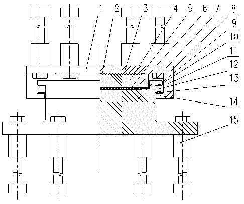
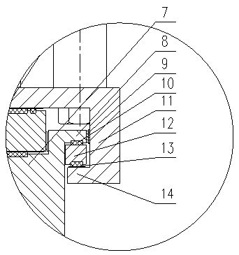
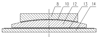
[0032] Such as image 3 As shown, the lower part of the lug 8 of the lower seat plate of the pull-out-resistant structure is provided with a concave arc-shaped structure. The surface of the arc structure is covered with a friction plate with a low coefficient of friction and matches with the upward convex arc surface of the rotary slider 12 to form a rotary friction pair of the rotary slider to adapt to the longitudinal rotation of the upper beam.
[0033] The lower plane of the rotating slider 12 of the anti-drawing structure is coated with a friction plate with a low friction coefficient and matched with the stainless steel sliding plate coated on the upper surface of the upper seat plate tensile plate 14 to form a plane friction pair of the rotating slider. To accommodate the longitudinal displacement of the upper beam body.
Embodiment 2
[0035] Such as Figure 4 As shown, the lower part of the lug 8 of the lower seat plate of the pullout-resistant structure is provided with a convex arc-shaped structure. The surface of the arc structure is covered with a friction plate with a low coefficient of friction and matches the upper concave arc surface of the rotary slider 12 to form a rotary friction pair of the rotary slider to adapt to the longitudinal rotation of the upper beam.
[0036] The lower plane of the rotating slider 12 of the anti-drawing structure is coated with a friction plate with a low friction coefficient and matched with the stainless steel sliding plate coated on the upper surface of the upper seat plate tensile plate 14 to form a plane friction pair of the rotating slider. To accommodate the longitudinal displacement of the upper beam body.
Embodiment 3
[0038] Such as Figure 5 As shown, the lower part of the rotating slider 12 of the anti-pullout structure is provided with a convex arc-shaped structure. The surface of the arc-shaped structure is covered with a friction plate with a low coefficient of friction and matches the upper concave arc surface of the upper seat plate tensile plate 14 to form a rotating friction pair of the rotating slider to adapt to the longitudinal rotation of the upper beam.
[0039] The lower surface of the lug 8 of the lower seat plate of the anti-drawing structure is covered with a friction plate with a low friction coefficient and matches with the stainless steel slide plate coated on the upper surface of the rotating slider 12 to form a plane friction pair of the rotating slider. To accommodate the longitudinal displacement of the upper beam body.
PUM
 Abstract
Description
Claims
Application Information
 - Generate Ideas
- Intellectual Property
- Life Sciences
- Materials
- Tech Scout
- Unparalleled Data Quality
- Higher Quality Content
- 60% Fewer Hallucinations
Browse by: Latest US Patents, China's latest patents, Technical Efficacy Thesaurus, Application Domain, Technology Topic, Popular Technical Reports.
© 2025 PatSnap. All rights reserved.Legal|Privacy policy|Modern Slavery Act Transparency Statement|Sitemap|About US| Contact US: help@patsnap.com


