
Three-freedom-degree weak coupling resonant accelerometer based on modal localization effect

An accelerometer and localized technology, applied in the field of sensors, can solve the problems that the initial working point of the accelerometer cannot be determined, the measurement range of the working point is difficult to adjust flexibly, and the design of the closed-loop circuit of the working mode is difficult, so as to achieve flexible selection and linear operation. Range adjustment, improving stability and accuracy, reducing the effect of coupling

Active Publication Date: 2018-01-30
NORTHWESTERN POLYTECHNICAL UNIV
View PDF5 Cites 32 Cited by
  • Summary
  • Abstract
  • Description
  • Claims
  • Application Information

AI Technical Summary

Problems solved by technology

However, there are still many aspects to be improved in terms of structural design of the accelerometer.
For example, the differential detection method is not used for a single resonator, resulting in the output signal of the test will be interfered by the feedthrough capacitance signal between the resonator drive electrode and the detection electrode, which greatly reduces the effective signal amplitude; the weak accelerometer The coupled resonator consists of a double-ended fixed tuning fork structure, which is driven from both ends of the resonator at the same time. This design makes the resonator structure have four operating modes, which gives the choice of operating modes and the design of closed-loop circuits It has brought great difficulties; due to the structural mismatch caused by the processing error to the two weakly coupled resonators, the initial working point of the accelerometer cannot be determined, and it is difficult to flexibly adjust the working point and the linear measurement range
More importantly, the core sensitive structure of the accelerometer is a two-degree-of-freedom weakly coupled resonator, and its mode localization is limited, which limits the further improvement of the accuracy of the accelerometer.

Method used


Image

  • Three-freedom-degree weak coupling resonant accelerometer based on modal localization effect
  • Three-freedom-degree weak coupling resonant accelerometer based on modal localization effect
  • Three-freedom-degree weak coupling resonant accelerometer based on modal localization effect

Examples


Embodiment Construction

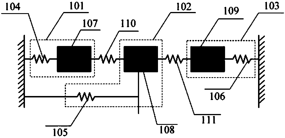
[0016] Before introducing the present invention in detail, the mode localization principle based on the weakly coupled resonant system involved in the present invention and the theoretical basis for applying the sensing mechanism to the field of acceleration detection are firstly introduced. figure 1 It is a schematic diagram of a simplified spring-mass model of a three-degree-of-freedom resonant system. The three-degree-of-freedom resonant system consists of resonator one equivalent 101, resonator two equivalent 102, and resonator three equivalent 103, as well as coupling beams and fixed anchor points composition. In the three-degree-of-freedom weak-coupling resonator designed in the present invention, the resonator one equivalent 101 and the resonator three equivalent 103 are completely symmetrical, in figure 1 In , springs are used as the stiffness models 110 and 111 of the mechanically coupled beam to equivalently represent the stiffness k of the coupled beam c , its mass...


PUM


Abstract

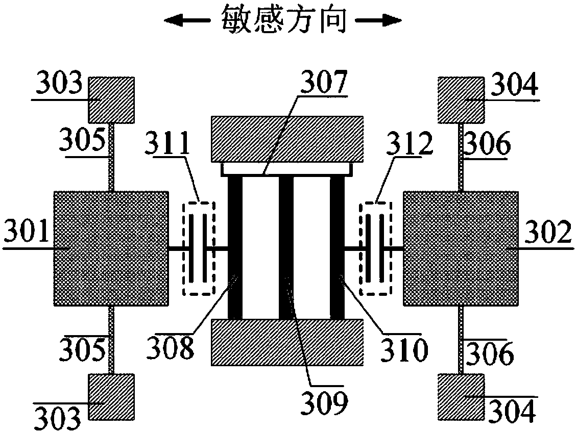
The invention discloses a micro resonant accelerometer based on the principle of modal localization, which belongs to the field of micro-electromechanical systems (MEMS). The accelerometer consists oftwo identical movable masses and three resonators connected together through a mechanical coupling beam. According to the invention, the three-freedom-degree weak coupling resonators are used to further improve the sensitivity of the resonators, and the sensitivity of the accelerometer is improved; capacitor plates are arranged on inner and outer sides of each resonator; amplitude differential detection is carried out on a single resonator, which can enhance the signal intensity and eliminates feedthrough capacitor signal interference caused by the potential difference between a drive electrode and a detection electrode; the stability and accuracy of a measurement signal can be greatly enhanced; a stiffness adjustment electrode is added; and flexible working point selection and linear working scope adjustment are realized.

Description

[0001] Field: [0002] The invention relates to an acceleration sensor, in particular to a miniature resonant accelerometer based on mode localization effect, and belongs to the technical field of sensors. Background technique: [0003] The accelerometer is an instrument used to measure the acceleration of the carrier. It is the basic core component of the inertial navigation system. It has important application value in aerospace, automotive industry, consumer electronics, construction machinery and other fields. With its many advantages such as small size, light weight, low cost and easy mass production, MEMS accelerometer has become the main development direction of accelerometer. The working principle of most MEMS accelerometers is based on Newton's second law, which uses a movable mass to generate inertial force, and converts the inertial force into voltage, current or frequency changes through electrostatic, piezoresistive, piezoelectric or resonance sensing mechanisms ...

Claims


Application Information

Patent Timeline
Patent Type & Authority Applications(China)
IPC IPC(8): G01P15/097
Inventor 常洪龙康昊杨晶
Owner NORTHWESTERN POLYTECHNICAL UNIV
Learn More