
Threaded fan case

A technology for fan casing and thread assembly, which is applied to the components of pumping devices for elastic fluids, mechanical equipment, machines/engines, etc. Impervious stress, no statistical law of offset position, etc., to shorten the processing time, increase the rigidity of the casing, and reduce the probability of hitting the base

Active Publication Date: 2019-08-23
AECC SHENYANG ENGINE RES INST
View PDF6 Cites 0 Cited by
  • Summary
  • Abstract
  • Description
  • Claims
  • Application Information

AI Technical Summary

Problems solved by technology

[0004] 1. Since the upper edge plate of each stator blade is welded separately, there are many weld seams, and the upper edge plate of the stator is prone to impenetrable welding or excessive stress, and cracks are prone to occur;
[0005] 2. After the welding and heat treatment of the stator blades, the actual angular and axial positions of the blade body deviate from the theoretical position, the overall shrinkage of the casing and the flow path data deviate, which affects the aerodynamic stability, and the deviation position has no statistical law;
[0006] 3. When the axial distance between the stator blade and the rotor blade of the next stage is small, since the rear flange of the casing is outside the welding stress zone of the upper edge plate, the axial length of the wear-resistant coating above the rotor blade of the next stage is reserved Insufficient, there is a risk that the tip of the rotor will be ground to the base of the fan casing. If the axial length of the wear-resistant coating is guaranteed, the flange edge is within the dangerous distance of the welding seam of the upper edge plate, and cracks are easy to initiate;
[0007] 4. When the thickness of the stator blade is large and the blade shape changes greatly, a larger upper edge plate of the stator is required, which will cause a small circumferential margin and insufficient strength reserve after the casing is milled out of a special-shaped hole;
[0008] 5. Due to maintenance needs, it is necessary to add a maintenance seat in the axial area where the stator blade is located. When the welding scheme is adopted, the welding seam of the maintenance seat and the welding seam of the upper edge plate are close or even cross, and cracks are easy to initiate. The assembly scheme requires a milling machine The outer surface of the box affects the batch production speed

Method used


Image

  • Threaded fan case
  • Threaded fan case

Examples


Embodiment Construction

[0033] In order to make the objectives, technical solutions and advantages of the present invention clearer, the technical solutions in the embodiments of the present invention will be described in more detail below in conjunction with the drawings in the embodiments of the present invention.

[0034] It should be noted that: in the drawings, the same or similar symbols represent the same or similar elements or elements with the same or similar functions. The described embodiments are part of the embodiments of the present invention, but not all of the embodiments. In the case of no conflict, the embodiments in the present application and the features in the embodiments can be combined with each other. Based on the embodiments of the present invention, all other embodiments obtained by persons of ordinary skill in the art without creative efforts fall within the protection scope of the present invention.

[0035] In describing the present invention, it is to be understood that...


PUM


Abstract

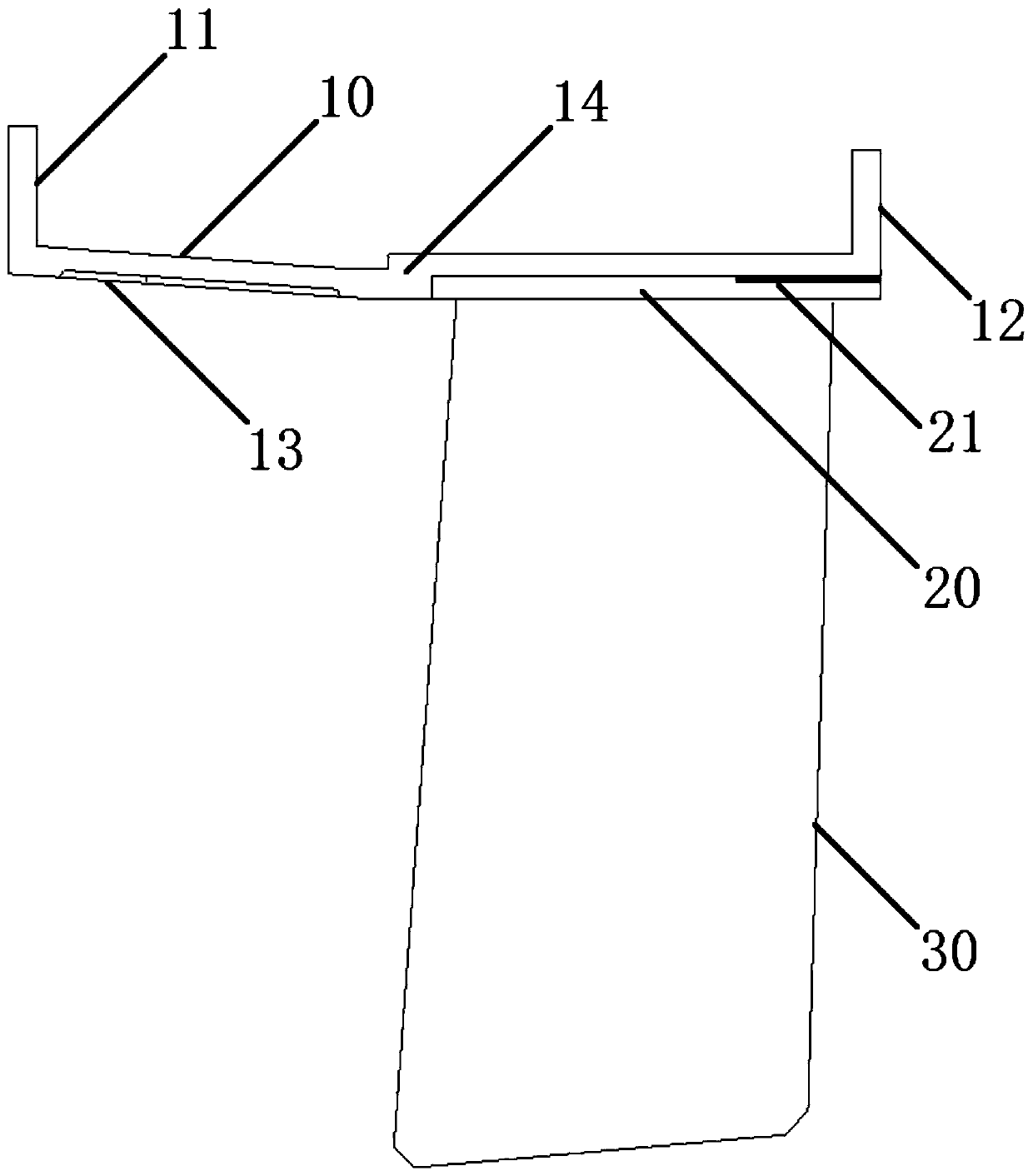
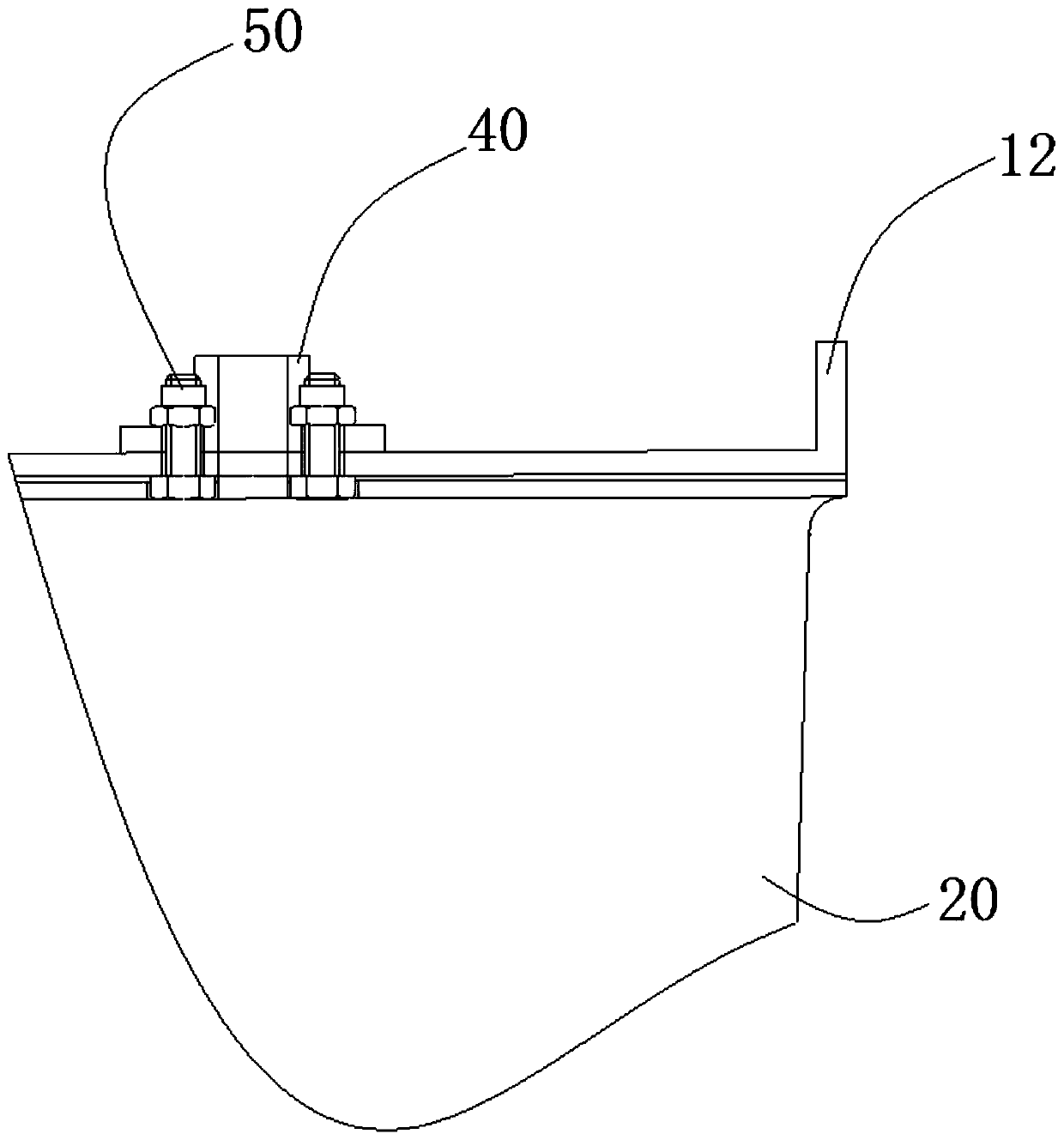
The invention relates to the technical field of aero-engines and particularly provides a fan cartridge receiver assembled through a thread. A machining scheme of welding the cartridge receiver and each stator blade is adjusted into a scheme of screwing a whole ring of stator blades with a second outer ring into a first outer ring, welding and heat treatment processes are omitted, the problems of insufficient abrasion-resistant coating axial length, large-margin-plate small cartridge receiver allowance and the like caused by cartridge receiver deformation, stator blade body malposition and small axial clearances of the stator blades are solved, and the vibration-resistant capability of the cartridge receiver is improved.

Description

technical field [0001] The invention relates to the technical field of aero-engines, in particular to a screw-assembled fan casing. Background technique [0002] At present, the whole ring casing generally adopts welding type: special-shaped holes are milled on the thin-walled casing, and the special-shaped holes are matched with the small gap of the upper edge plate of the stator and then welded by electron beam welding, so that the structure is simplified. [0003] The traditional welded fan case has the following defects: [0004] 1. Since the upper edge plate of each stator blade is welded separately, there are many weld seams, and the upper edge plate of the stator is prone to impenetrable welding or excessive stress, and cracks are prone to occur; [0005] 2. After the welding and heat treatment of the stator blades, the actual angular and axial positions of the blade body deviate from the theoretical position, the overall shrinkage of the casing and the flow path dat...

Claims


Application Information

Patent Timeline
Patent Type & Authority Patents(China)
IPC IPC(8): F04D29/40F04D29/60F04D29/02
Inventor 项洁琼罗红斌姜大成胡丹赵旭辉
Owner AECC SHENYANG ENGINE RES INST
Learn More