
Vertical partition plate beam and column connection joint applicable to composite steel plate shear wall end column and construction method for applying vertical partition plate beam and column connection joint

A combined shear wall and beam-column connection technology, applied to walls, buildings, building components, etc., can solve the problems of large space occupation, complex construction process, poor seismic performance, etc., achieve rapid construction and solve low processing efficiency , the effect of ensuring the compactness

Pending Publication Date: 2018-01-30
HUNAN ARCHITECTURAL DESIGN INST +1
View PDF6 Cites 0 Cited by
  • Summary
  • Abstract
  • Description
  • Claims
  • Application Information

AI Technical Summary

Problems solved by technology

[0003] In order to solve the technical problems of poor seismic performance of existing beam-column joints, large space occupation, complicated construction procedures, inconvenient transportation, and high cost, the present invention provides a targeted anti-seismic performance that occupies a small space. The construction process is simple, the transportation is convenient, and the cost is not high. It is suitable for the vertical diaphragm beam-column connection node and its application method for the end column of the steel plate composite shear wall.

Method used

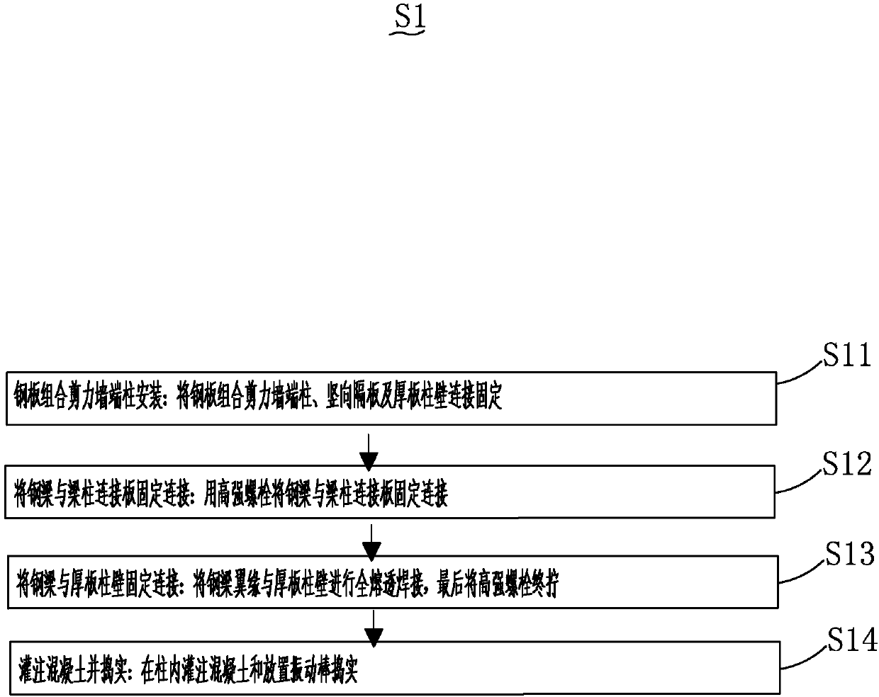

Image

  • Vertical partition plate beam and column connection joint applicable to composite steel plate shear wall end column and construction method for applying vertical partition plate beam and column connection joint
  • Vertical partition plate beam and column connection joint applicable to composite steel plate shear wall end column and construction method for applying vertical partition plate beam and column connection joint

Examples


Embodiment Construction

[0025] The following will clearly and completely describe the technical solutions in the embodiments of the present invention with reference to the accompanying drawings in the embodiments of the present invention. Obviously, the described embodiments are only some, not all, embodiments of the present invention. Based on the embodiments of the present invention, all other embodiments obtained by persons of ordinary skill in the art without making creative efforts belong to the protection scope of the present invention.

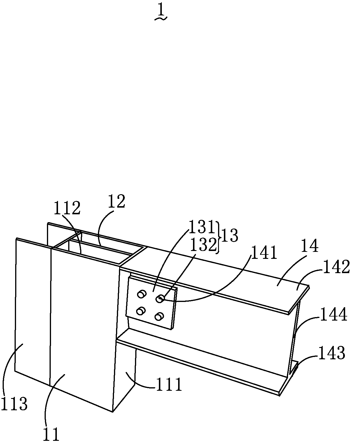
[0026] see figure 1 , is a structural schematic diagram of a preferred embodiment of the vertical partition beam-column connection node suitable for the end columns of steel plate composite shear walls provided by the present invention.

[0027] The vertical partition beam-column connection node 1 applicable to the end column of the steel plate composite shear wall includes an end column 11 of the steel plate composite shear wall, a vertical partition 12 , a b...


PUM


Abstract

The invention provides a vertical partition plate beam and column connection joint applicable to a composite steel plate shear wall end column and a construction method for applying the vertical partition plate beam and column connection joint. The vertical partition plate beam and column connection joint applicable to the composite steel plate shear wall end column comprises the composite steel plate shear wall end column, a vertical partition plate, a beam and column connection plate and a steel beam. The vertical partition plate is vertically arranged in the opposite insides of the composite steel plate shear wall end column, the composite steel plate shear wall end column comprises a thick plate column wall, the thick plate column wall is arranged on a side of the composite steel plateshear wall end column, and the beam and column connection plate is connected with the steel beam and the thick plate column wall. The vertical partition plate beam and column connection joint applicable to the composite steel plate shear wall end column and the construction method have the advantages that the vertical partition plate beam and column connection joint in a connection mode is provided with the vertical partition plate, accordingly, the steel beam can be effectively connected with a composite steel plate shear wall, and requirements of pouring concrete construction methods can bemet.

Description

technical field [0001] The invention belongs to the technical field of construction engineering, and in particular relates to a vertical partition beam-column connecting node suitable for an end column of a steel plate composite shear wall and a construction method thereof. Background technique [0002] At present, the traditional forms of steel structure beam-column connection include partition through connection, column through connection and outer ring plate connection. For the connection between steel beam and closed section column, the first two forms need to open a round hole in the center of the partition , and the diameter of the hole needs to meet the requirements of concrete pouring and vibration, but the hole with a diameter of not less than 150mm greatly weakens the force transmission effect of the diaphragm in the end column of the small-section steel plate composite shear wall, and affects the seismic resistance of the beam-column joint Performance, if the oute...

Claims


Application Information

Patent Timeline
Patent Type & Authority Applications(China)
IPC IPC(8): E04B2/58E04B1/24E04B1/58E04B2/56
Inventor 周泉王四清蒋丽忠
Owner HUNAN ARCHITECTURAL DESIGN INST
Learn More