Drainage valve with drainage speed variable at drainage state

A drainage valve and variable technology, applied in water supply devices, flushing equipment with water tanks, buildings, etc., can solve the problems of constant, poor flushing and decontamination effects, etc., and achieve the effect of extending drainage time and good decontamination effect

Pending Publication Date: 2018-01-30
厦门标尔玛卫浴科技有限公司
View PDF0 Cites 1 Cited by
  • Summary
  • Abstract
  • Description
  • Claims
  • Application Information

AI Technical Summary

Problems solved by technology

There are many drain valve structures for this single-row button, but generally in the drain state, the drain speed is constant, and the effect of flushing and decontamination is poor.

Method used


Image

  • Drainage valve with drainage speed variable at drainage state
  • Drainage valve with drainage speed variable at drainage state
  • Drainage valve with drainage speed variable at drainage state

Examples


Embodiment Construction

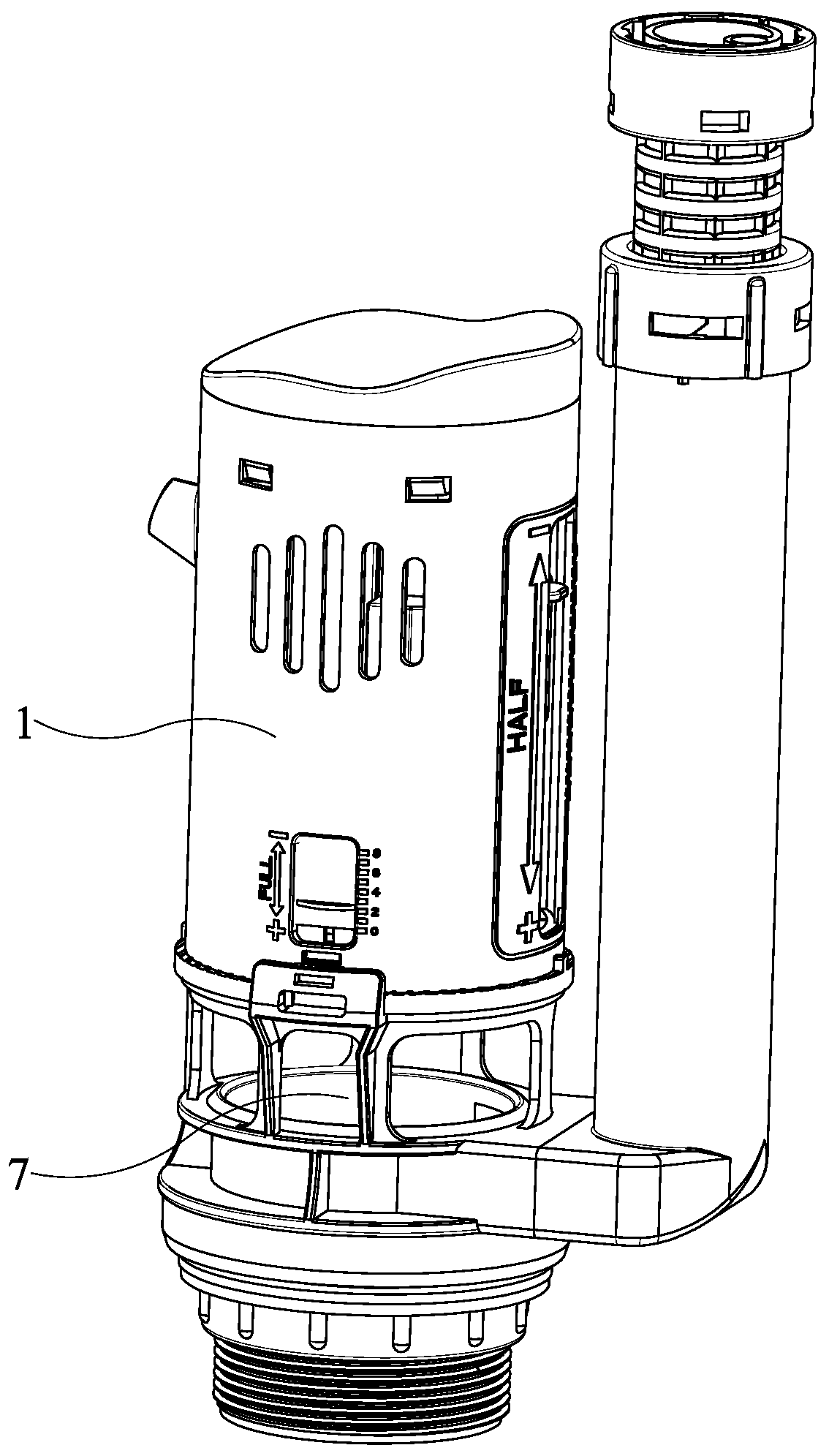
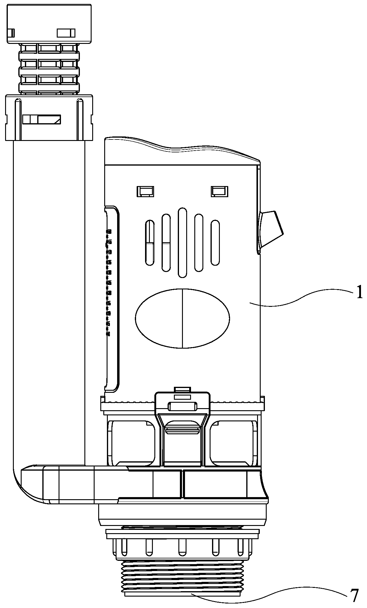
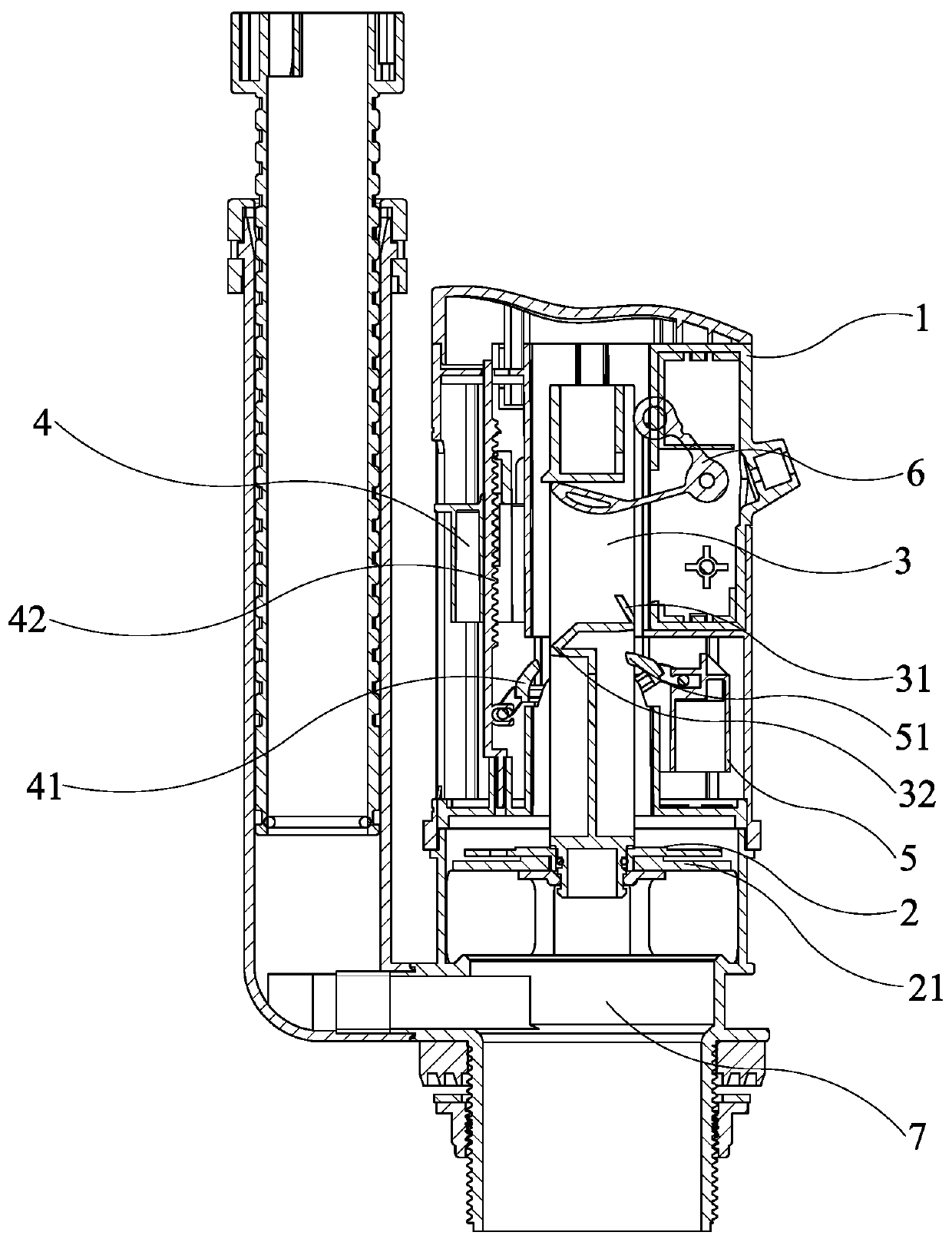
[0022] like Figure 1 to Figure 7 As shown in the figure, a variable discharge valve in the discharge state disclosed by the present invention includes a button (a common component, not shown in the figure), a valve body 1, a valve seat 2, a valve core 3, a fast discharge buoy 4 and a slow discharge buoy 5.

[0023] The button is driven on the spool 3. As shown in the figure, the button can be connected to one end of the wire-controlled pendulum hook 6 through a pull wire. Pulling the wire-controlled pendulum hook 6 drives the spool 3 to lift up. The button can also drive the spool 3 to be lifted through the transmission rod assembly.

[0024] The valve seat 2 is installed at the lower end of the spool 3 for facing the water outlet 7 of the toilet, and the water-stop gasket 21 is installed on the valve seat 2. The spool 3 has a fast-discharging card position 32 and a slow-discharging card position 31 . As shown in the figure, the fast row card slot 32 is located below the...


PUM


Abstract

The invention discloses a drainage valve with drainage speed variable at the drainage state. The drainage valve comprises a button, a valve body, a valve seat, a valve spool, a fast-drainage float barrel and a slow-drainage float barrel; the button is in transmission with the valve spool; the lower end of the valve spool is provided with the valve seat with a waterstop sealing pad and rightly facing to the outer outlet of a toilet, and a fast-drainage buckling position and a slow-drainage buckling position are arranged on the valve spool; the fast-drainage float barrel and the slow-drainage float barrel are mounted on the valve body, the fast-drainage float barrel is located above the slow-drainage float barrel, a fast-drainage buckle mounted on the fast-drainage barrel is used for being correspondingly fitted with fast-drainage buckling position on the valve spool to achieve fast drainage in the early stage of drainage, and a slow-drainage buckle mounted on the slow-drainage barrel isused for being correspondingly matched the slow-drainage buckling position on the valve spoon to achieve slow drainage in the last stage of drainage. Siphon is established by supplying sufficient water from the beginning, the minimum critical amount of the water required by siphon is kept after the siphon is established, good removal effect is achieved, and meanwhile, drainage time can be prolonged for subsequent water supply.

Description

technical field [0001] The invention relates to a variable discharge valve in discharge state and discharge speed. Background technique [0002] Usually, when the displacement of the toilet is about 3L, the drain valve of the toilet no longer distinguishes the full row and the half row, that is, there is only one button for the single row. It is stuck on the deflection buckle on the buoy and cannot go down, so that the water-stop gasket at the lower end of the valve core leaves the water outlet on the valve seat to realize drainage. When the water level drops below the buoy, the buoy deflects, making the water on the buoy The deflection buckle is separated from the locking position on the valve core, and the valve core falls under the action of gravity, so that the water-stop sealing gasket is covered on the water outlet to realize water-stop. And there are many drainage valve structures of this single-row button, but generally in the drainage state, the drainage speed is c...

Claims


Application Information

Patent Timeline
IPC IPC(8): E03D1/35E03D5/092E03D5/094
Inventor 高仁宏
Owner 厦门标尔玛卫浴科技有限公司
Why Eureka
Try Eureka