
Hydraulic tensioning device

A tensioning device, hydraulic technology, applied in the direction of transmission, belt/chain/gear, mechanical equipment, etc., can solve the problem of difficult installation of locking parts, and achieve the effect of simple installation and easy passage

Inactive Publication Date: 2018-01-26
SCHAEFFLER TECH AG & CO KG
View PDF0 Cites 0 Cited by
  • Summary
  • Abstract
  • Description
  • Claims
  • Application Information

AI Technical Summary

Problems solved by technology

[0005] The problem to be solved by the present invention is: it is difficult to install the locking parts for transportation of the existing hydraulic tensioning device

Method used


Image

  • Hydraulic tensioning device
  • Hydraulic tensioning device
  • Hydraulic tensioning device

Examples


Embodiment Construction

[0021] In order to make the above objects, features and advantages of the present invention more comprehensible, specific embodiments of the present invention will be described in detail below in conjunction with the accompanying drawings.

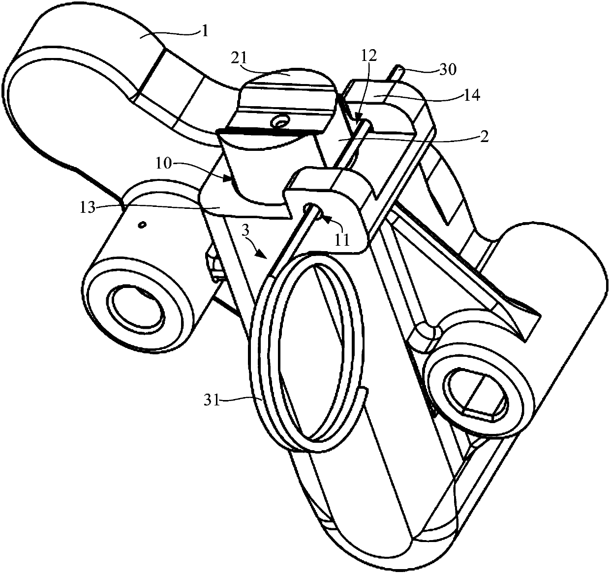
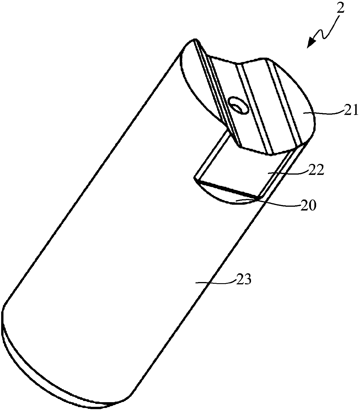
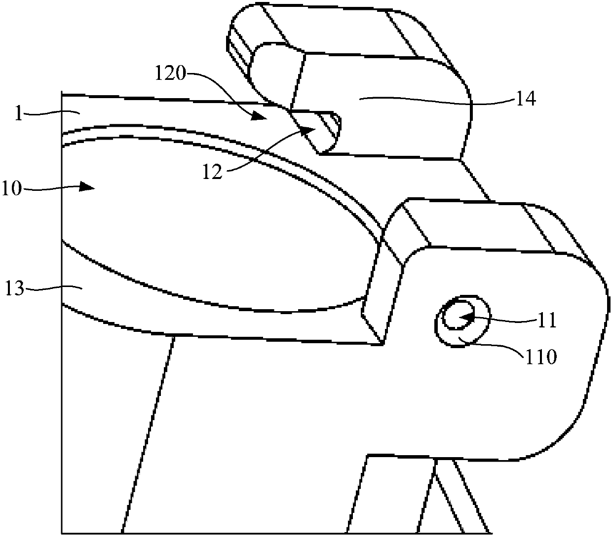
[0022] combine Figure 1 to Figure 3 As shown, the hydraulic tensioning device of this embodiment includes a housing 1 and a plunger 2 . Wherein, the casing 1 is provided with a plunger hole 10 , and the plunger 2 is located in the plunger hole 10 so as to be able to move axially. The plunger 2 has an end surface 21 extending out of the plunger hole 10 , and the outer peripheral surface of the plunger 2 has a step 20 . The casing 1 is provided with a receiving through hole 11 and a receiving channel 12, and the receiving through hole 11 and the receiving channel 12 are arranged at intervals. The transport locking piece 3 passes through the receiving through hole 11 and the receiving channel 12 successively, and is located on the outside ...


PUM


Abstract

The invention discloses a hydraulic tensioning device. The device comprises a shell, a plunger, an accommodating through hole and an accommodating channel, wherein the shell is provided with a plungerhole; the plunger is axially movably located in the plunger hole; a step is arranged on the outer peripheral surface of the plunger; the accommodating through hole and the accommodating channel are arranged at intervals on the shell and are used for accommodating a locking piece for transportation; the locking piece for transportation is located on the outer side of the step in the axial direction; and the accommodating channel is provided with a notch. According to the hydraulic tensioning device, the space of the accommodating channel for enabling the locking piece for transportation to enter is increased, the locking piece for transportation can penetrate through the accommodating channel more easily and installation of the locking piece for transportation is simpler.

Description

technical field [0001] The invention relates to a hydraulic tensioning device for maintaining the tension of the chain drive system of an internal combustion engine. Background technique [0002] The hydraulic tensioner is a control device widely used in the chain transmission system of the internal combustion engine of the automobile. Its function is to maintain the tension of the chain in the chain transmission system of the internal combustion engine to reduce the vibration of the chain and ensure its normal operation. An existing hydraulic tensioning device includes a housing provided with a plunger hole and a plunger axially movable in the plunger hole, and the outer peripheral surface of the plunger has steps. [0003] Before installing the hydraulic tensioning device to the internal combustion engine, in order to prevent the plunger from being separated from the casing due to axial movement during transportation, there is an existing solution: two accommodating passag...

Claims


Application Information

Patent Timeline
IPC IPC(8): F16H7/08
Inventor 刘琦盛
Owner SCHAEFFLER TECH AG & CO KG
Learn More