
Patsnap Eureka
For R&D, Patsnap Eureka makes reading and utilizing patents & technical documents easy.
Patsnap Eureka AIR
Designed for self-driven R&D workflows. Generate viable solutions, solve complex R&D challenges, empower your innovation with AI.

Patsnap Eureka Materials
Designed for material experts only. Revolutionize your material R&D, from search, analyze, to developing new materials.

TechResearch
Generate reliable direction feasibility study reports for your R&D in just a few steps.

TechSeek
Discover and master advanced knowledge NOW. Basics, ideas, possibilities, all at once.

TechMind
As an expert in R&D Theories, TechMind can generates customized viable solutions instantly.

TechRisk
Analyze your overall solution with one click, know your potential R&D risks in advance.

TechMonitor
Get weekly tech updates, stay abreast of the latest tech innovations and key insights.
Automatic cleaning, drying and conveying device
A conveying device and automatic cleaning technology, applied in the direction of drying solid materials, drying solid materials without heating, drying, etc., can solve the problems of single function, difficult to transport and clean items, unclean bottom of packaging boxes, etc.
- Summary
- Abstract
- Description
- Claims
- Application Information
AI Technical Summary
Problems solved by technology
Method used
Image

Examples
Embodiment 1
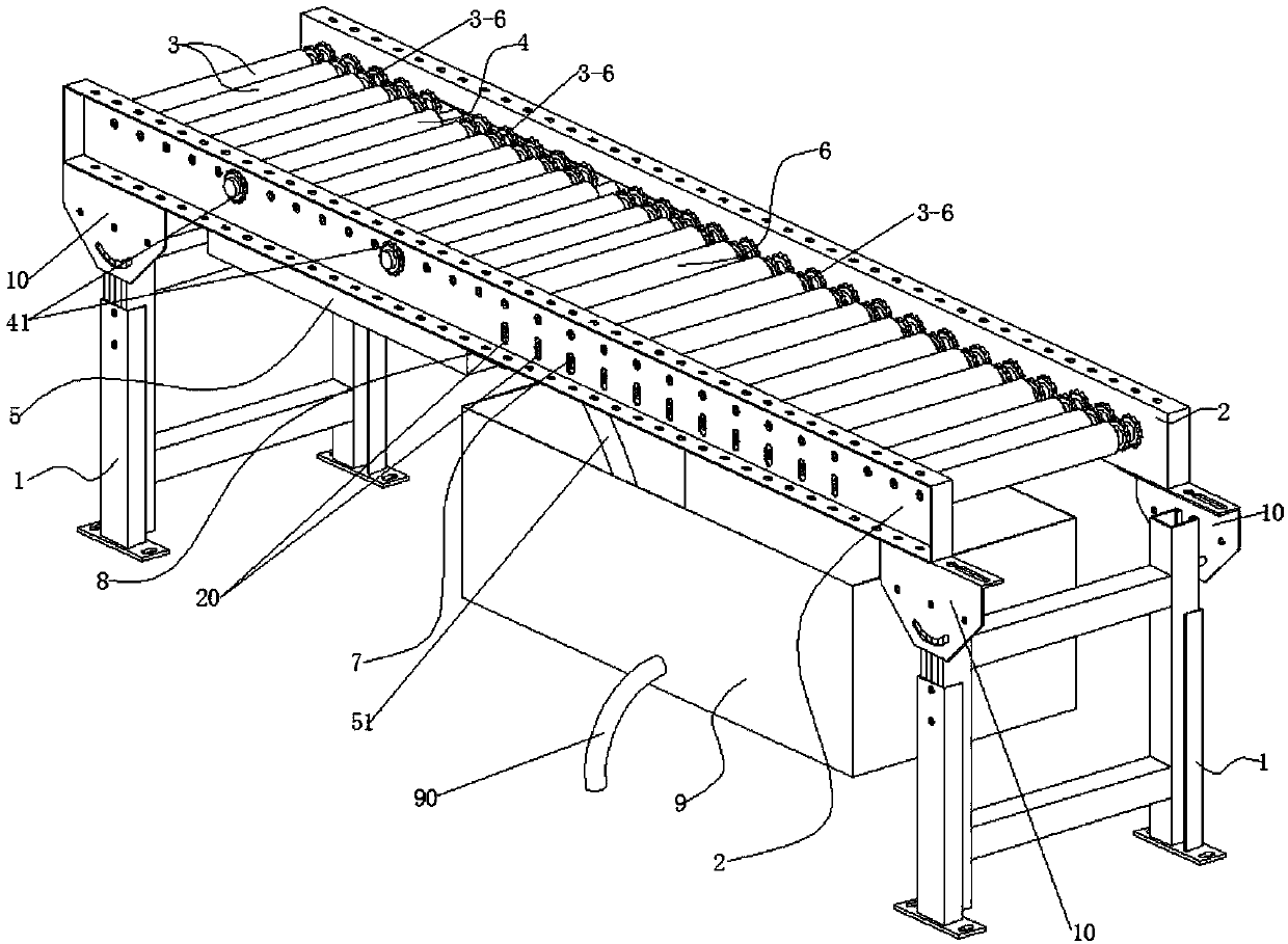
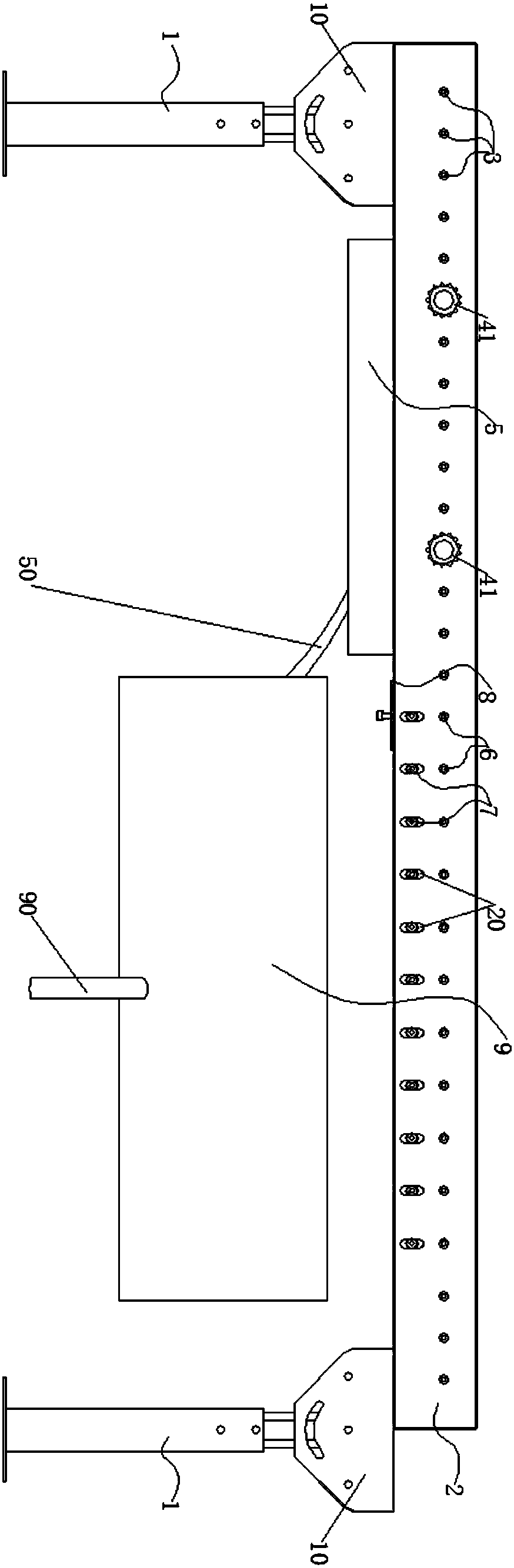
[0039]The automatic cleaning and drying conveying device places the articles to be conveyed on the conveying roller 3, and the external power source simultaneously drives the conveying roller 3 and the cleaning roller through the chain with the single-row sprocket 41 and the double-row sprocket 3-6. The cylinder 4 and the suction roller 6 rotate, and the articles pass through the cleaning roller 4 during transportation, and because the cleaning roller 4 is provided with a brush 40, the washing water tank 5 is located directly below the cleaning roller 4, and It is connected with the side sill plate 2 by bolts, so the brush 40 on the cleaning roller 4 can carry the clean water in the washing tank 5 to clean the bottom of the conveyed items, and after the cleaning is completed, it will be transported by the conveying roller 3 to the On the water absorption roller 6, because the water absorption roller 6 is covered with a water absorption layer 60, and the water absorption layer 6...
Embodiment 2
[0042] When the pressure roller system adjustment assembly 1-1 is used to squeeze and drain water, the cylinder 1-11 shrinks with its piston rod, and the piston rod pulls the connecting rod 1-12 to move upward, so that the connecting rod 1-13 simultaneously brings A plurality of extrusion rollers 7 move upwards and press on the water-absorbing layer 60 corresponding to the outer layer of the water-absorbing roller 6. By changing the stroke of the cylinder 1-11 and controlling the extrusion force, extrusion drainage is realized, which is convenient for repeated use , one-time extrusion drainage, higher drainage efficiency.
[0043] The connecting rods 1-12 are in the shape of "a few", which ensures the stability of the movement of the connecting rods 1-13 without inclination, and ensures that the extrusion force of the water-absorbing layer 60 on the surface of each water-absorbing roller 6 is the same; The lower end of the scrubbing water tank 5 is provided with a drainpipe 1 ...
PUM
 Abstract
Description
Claims
Application Information
 - R&D Engineer
- R&D Manager
- IP Professional
- Industry Leading Data Capabilities
- Powerful AI technology
- Patent DNA Extraction
Browse by: Latest US Patents, China's latest patents, Technical Efficacy Thesaurus, Application Domain, Technology Topic, Popular Technical Reports.
© 2024 PatSnap. All rights reserved.Legal|Privacy policy|Modern Slavery Act Transparency Statement|Sitemap|About US| Contact US: help@patsnap.com