
A 3D contact angle testing device and method using a polygonal mirror to refract the light path

A technology of reversing the optical path and testing device, applied in the direction of measurement device, instrument, surface/boundary effect, etc., can solve the problems of poor image synchronization, complicated operation, and inability to measure the contact angle comprehensively and accurately.

Active Publication Date: 2020-12-11
上海梭伦信息科技有限公司
View PDF7 Cites 0 Cited by
  • Summary
  • Abstract
  • Description
  • Claims
  • Application Information

AI Technical Summary

Problems solved by technology

[0005] The technical problem to be solved by the present invention is to provide a 3D contact angle testing device and testing method using a polygonal mirror to refract the optical path, which solves the problem of inaccurate measurement, complicated operation, and inability to fully and accurately measure the current contact angle measuring device. The problem of contact angle and poor synchronization between different images under the condition of multiple viewing angles

Method used


Image

  • A 3D contact angle testing device and method using a polygonal mirror to refract the light path
  • A 3D contact angle testing device and method using a polygonal mirror to refract the light path
  • A 3D contact angle testing device and method using a polygonal mirror to refract the light path

Examples


Embodiment 1

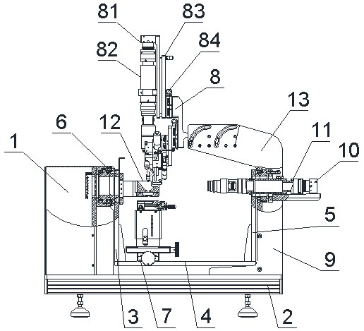
[0057] Such as Figure 4 and Figure 6 As shown, the prism 3D contact angle lens 12 is a 180 degree 3D contact angle lens, and the 180 degree 3D contact angle lens includes two second rectangular prisms 124 and two mounting frames 122, and the two mounting frames 122 are respectively fixed on Two second rectangular prisms 124 are oppositely arranged between the two mounting frames 122 on the opposite sides of the mounting seat 121 so that the slopes of the two are facing and the front ends are against each other. The front ends of the second rectangular prisms 124 are respectively opened and installed The same semicircular hole of seat 121 central through hole diameter, is provided with triangular light-shielding block between two second rectangular prisms 124, and the first rectangular prism 123 is a total inverse rectangular prism, the first rectangular prism 123 oblique faces downward, two rectangular faces They are respectively arranged in the through holes of the mountin...

Embodiment 2

[0062] Such as Figure 7 and Figure 8 As shown, the multi-prism 3D contact angle lens 12 is a 360-degree 3D contact-angle lens, and the 360-degree 3D contact-angle lens includes several first right-angle prisms 123 and a second right-angle prism 124, and also includes a second right-angle prism fixing frame 125, the second rectangular prism 124 is a total inversion rectangular prism, the first rectangular prism 123 is a transflective rectangular prism, the second rectangular prism holder 125 is fixed on the mount 121, and the second rectangular prism 124 is fixed Be positioned at the top of the first right-angled prism 123 on the second right-angled prism holder 125, the slope of the second right-angled prism 124 is downward, two right-angled surfaces are parallel with vertical plane and horizontal plane respectively, the slope of the first right-angled prism 123 is upward, The two right-angled planes are respectively arranged in the through hole of the mounting base 121 par...


PUM


Abstract

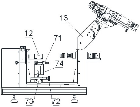
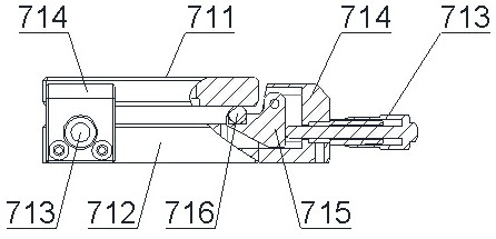
The invention discloses a 3D contact angle test device and method using a polygon prism reflective light path, and belongs to the technical field of a contact angle measuring device. The device comprises an electric control box, a bottom plate, a first vertical connecting plate, a transverse connecting plate, a second vertical connecting plate, a step motor controlled optical rotating platform, aregulating platform assembly, an injection system, a support frame, a camera, a microscope and a polygon prism 3D contact angle lens, wherein the electric control box is provided with a background light source; the microscope is matched with the camera to be used; the polygon prism 3D contact angle lens comprises an installing seat, an installing frame, a plurality of first right-angle prisms anda second right-angle prism; the injection system is rotationally connected with the support frame through a turning support frame. The goal of synchronously and fast testing the 3D contact angle is achieved; the precision of the contact angle test is greatly improved; through the AOI technology, for the profile of each liquid drop, the 3D contact angle value is obtained through the ADSA-RealDrop algorithm.

Description

technical field [0001] The invention relates to a 3D contact angle testing device and method using a polygonal mirror to refract an optical path, and belongs to the technical field of contact angle measuring devices. Background technique [0002] Basic indicators such as liquid-liquid interfacial tension, liquid-gas surface tension, and solid-liquid contact angle are the basic parameters to characterize the physical and chemical properties of substances. The contact angle refers to the point where a small drop of liquid is dropped on a solid horizontal plane, and at the solid-liquid-gas three-phase junction point on the solid surface, the two tangent lines of the gas-liquid interface and the solid-liquid interface sandwich the liquid phase angle formed when . The contact angle value is an indicator comprehensively determined by various factors such as the inherent properties of the material itself, chemical isomerism, surface physical structure, and surface cleanliness. Du...

Claims


Application Information

Patent Timeline
Patent Type & Authority Patents(China)
IPC IPC(8): G01N13/00
Inventor 施建辉
Owner 上海梭伦信息科技有限公司
Learn More