Extrusion type deformation ring
An extruded and ring-shaped ring technology, which is applied to transmission parts, ring springs, springs/shock absorbers, etc., can solve the problems of large reducers, insufficient rigidity, and large rotational inertia, etc., to ensure that the center Output, eliminate radial assembly error and part processing error, and improve the effect of precision
- Summary
- Abstract
- Description
- Claims
- Application Information
AI Technical Summary
Problems solved by technology
Method used
Image

Examples
Embodiment 1
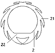
[0043] Such as figure 1 As shown, an extrusion-type deformation ring includes an annular ring body 2, and an elastic structural member is provided on the outer ring wall of the annular ring body.
[0044] The elastic structure includes two shrapnel groups symmetrical to each other, and each shrapnel group includes a number of shrapnels 21 distributed on the outer ring wall or half of the inner ring wall of the annular ring.
[0045] The annular ring body is correspondingly provided with a thickened area 22; the thickened area is located on the outer ring wall or the inner ring wall of the annular ring to form a corresponding arc surface; the thickened area is located on the inner ring of the annular ring The wall forms the inner horizontal line of the circle, and the outer ring wall of the annular circle forms the outer arc line of the circle.
[0046] Each shrapnel group includes a first shrapnel starting from one end of the outer ring wall of the annular ring or one half of t...
Embodiment 2
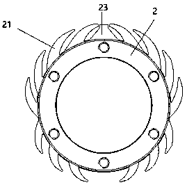
[0069] Such as figure 2 As shown, an extrusion-type deformation ring includes an annular ring body 2, and an elastic structural member is provided on the outer ring wall of the annular ring body.
[0070] In this embodiment, the elastic structure includes an elastic limiting boss 23 and shrapnel groups distributed symmetrically along both sides of the elastic limiting boss, and each shrapnel group includes a number of first shrapnel distributed on the outer ring wall of the annular ring Grouping and second shrapnel grouping, the first shrapnel grouping and the outer ring wall of the annular ring form an angle that is biased toward the elastic limit boss, and the second shrapnel grouping and the outer ring wall of the annular ring form a reverse elastic limiting The included angle of the boss.
[0071] Each shrapnel grouping includes the first shrapnel starting from the middle section of the half side of the outer ring wall of the annular ring, N middle shrapnel and the N+2th...
Embodiment 3
[0094] This embodiment discloses an extrusion-type deformation ring. The extrusion-type deformation ring includes an annular ring body. One of the differences between this embodiment and Embodiment 1 is that the inner ring wall of the annular ring body is provided with Elastic structure.
[0095] The elastic structure includes two shrapnel groups that are symmetrical to each other, and each shrapnel group includes a number of shrapnels distributed on the half side of the inner wall of the annular ring.
[0096] Each shrapnel group includes a first shrapnel starting from one half of the outer ring wall or the inner ring wall of the annular ring, two middle shrapnels and a fourth shrapnel ending at the other end of the inner ring wall half of the ring ring.
[0097] The root of each shrapnel is integrally connected with the outer ring wall or the inner ring wall of the annular ring, and the tail of each shrapnel forms an included angle with the inner ring wall of the annular rin...
PUM
 Abstract
Description
Claims
Application Information
 - R&D
- Intellectual Property
- Life Sciences
- Materials
- Tech Scout
- Unparalleled Data Quality
- Higher Quality Content
- 60% Fewer Hallucinations
Browse by: Latest US Patents, China's latest patents, Technical Efficacy Thesaurus, Application Domain, Technology Topic, Popular Technical Reports.
© 2025 PatSnap. All rights reserved.Legal|Privacy policy|Modern Slavery Act Transparency Statement|Sitemap|About US| Contact US: help@patsnap.com