Undercarriage of unmanned plane

A landing gear and unmanned aerial vehicle technology, applied in the field of unmanned aerial vehicles, can solve the problems of insufficient stability, rollover, and high manufacturing costs, and achieve the effect of avoiding flightlessness

Inactive Publication Date: 2018-01-19
四川道勤信业科技有限公司
View PDF1 Cites 7 Cited by
  • Summary
  • Abstract
  • Description
  • Claims
  • Application Information

AI Technical Summary

Problems solved by technology

[0002] At present, the landing gear of domestic rotorcraft mostly adopts the single-side-one-rod model, that is, the two sides of the aircraft are respectively equipped with T-shaped brackets. The traditional landing gear with this structure has a single structure and relatively poor support strength, and it is stable when landing. Insufficient, there is a possibility of rollover, and the manufacturing process generally adopts the one-piece manufacturing method, so the manufacturing cost is also high. In the prior art, such as the utility model patent with application number 201520457077.1, it includes two roughly inverted The three-way elbow joint of V-shaped structure and the support frame used as the supporting part of the UAV. The top connection ends of each three-way elbow joint are respectively connected to the two sides of the drone body. The lower connection end of the joint has two insertion openings respectively, each insertion opening is respectively inserted with a support frame, and the lower end of each support frame is respectively inserted into a three-way straight pipe with a roughly T-shaped structure, and each three-way The straight pipes also have a horizontal through hole, and connecting rods are inserted in the horizontal through holes of the two three-way straight pipes located on the same side of the UAV. Although this patent reduces the manufacturing cost, it is not easy to prevent the UAV from landing. In the process, the landing gear will collide with the ground. If the impact is strong, the inside of the UAV will be shaken. In severe cases, it may malfunction and affect the flight of the UAV.

Method used


Image

  • Undercarriage of unmanned plane
  • Undercarriage of unmanned plane
  • Undercarriage of unmanned plane

Examples


Embodiment Construction

[0015] The following will clearly and completely describe the technical solutions in the embodiments of the present invention with reference to the accompanying drawings in the embodiments of the present invention. Obviously, the described embodiments are only some, not all, embodiments of the present invention. Based on the embodiments of the present invention, all other embodiments obtained by persons of ordinary skill in the art without making creative efforts belong to the protection scope of the present invention.

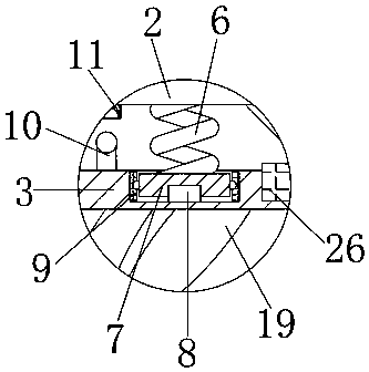
[0016] see Figure 1-4 , the present invention provides a technical solution: an unmanned aerial vehicle landing gear, including an unmanned aerial vehicle 1, an unmanned aerial vehicle is referred to as an unmanned aerial vehicle 1, and is an unmanned unmanned aerial vehicle operated by a radio remote control device and a self-provided program control device. Aircraft, or fully or intermittently autonomously operated by the on-board computer, the UAV 1 is buf...


PUM


Abstract

The invention discloses an undercarriage of an unmanned plane. The undercarriage comprises the unmanned plane, wherein the left side and the right side of the bottom end of the unmanned plane are respectively provided with a first connecting plate; second connecting plates are connected with first inner plates by convex blocks; undercarriages are arranged at the centers of the bottom ends of the second connecting plates; the centers of the inner sides of second inner plates are respectively provided with a supporting rod block; a plurality of first stopping blocks are arranged between the inner walls of the supporting rod blocks; first sliding rods are arranged between the first stopping blocks; the outer walls of the first sliding rods are respectively connected with a first sheathing plate in a sheathing manner; and second supporting rods are arranged at the centers between the inner sides of the first sheathing plates. According to the undercarriage disclosed by the invention, whenthe unmanned plane lands, by matching of the first connecting plates and the second connecting plates, the undercarriage can support the unmanned plane which is ready to land; and by buffering of thedevice, the unmanned plane is prevented from generating impact with the ground to avoid causing internal damage when in landing, and the failure of flying of the unmanned plane due to faults caused byimpact is effectively avoided.

Description

technical field [0001] The invention relates to the technical field of unmanned aerial vehicles, in particular to a landing gear for unmanned aerial vehicles. Background technique [0002] At present, the landing gear of domestic rotorcraft mostly adopts the single-side-one-rod model, that is, the two sides of the aircraft are respectively equipped with T-shaped brackets. The traditional landing gear with this structure has a single structure and relatively poor support strength, and it is stable when landing. Insufficient, there is a possibility of rollover, and the manufacturing process generally adopts the one-piece manufacturing method, so the manufacturing cost is also high. In the prior art, such as the utility model patent with application number 201520457077.1, it includes two roughly inverted The three-way elbow joint of V-shaped structure and the support frame used as the supporting part of the UAV. The top connection ends of each three-way elbow joint are respecti...

Claims


Application Information

Patent Timeline
Patent Type & Authority Applications(China)
IPC IPC(8): B64C25/62B64C39/02
Inventor 陈嫣
Owner 四川道勤信业科技有限公司
Why Eureka
Try Eureka