


Quick Research
Generate reliable direction feasibility study reports for your R&D in just a few steps.

Technical Q&A
Discover and master advanced knowledge NOW. Basics, ideas, possibilities, all at once.

Find Solutions
As an expert in R&D theories, this can generate solutions to your technical problems instantly.

Evaluate Feasibility
Analyze your overall solution with one click, know your potential R&D risks in advance.

Monitor Landscape
Get weekly tech updates, stay abreast of the latest tech innovations and key insights.
Artificial prosthesis
An artificial prosthesis and prosthesis technology, applied in the field of artificial prosthesis, can solve problems such as patient injury and excessive wear of joint prosthesis, and achieve the effect of reducing treatment costs
- Summary
- Abstract
- Description
- Claims
- Application Information
AI Technical Summary
Problems solved by technology
Method used
Image

Examples
Embodiment 1
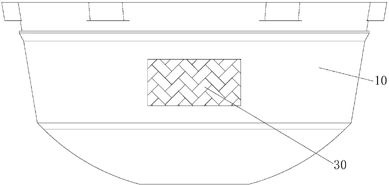
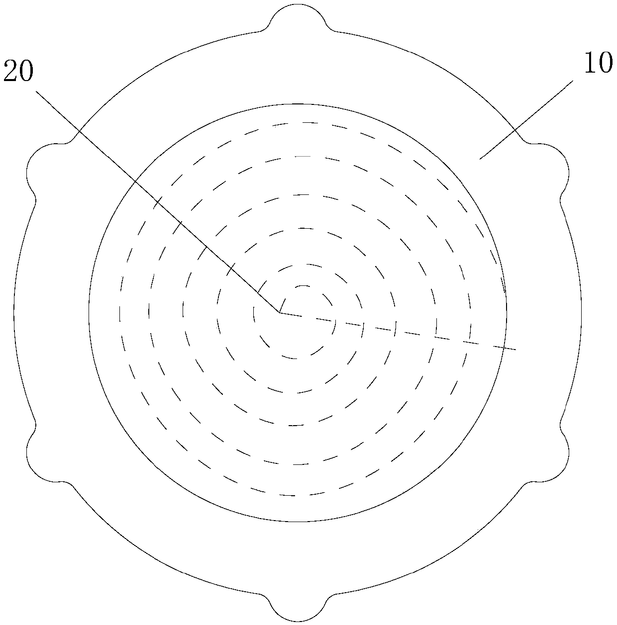
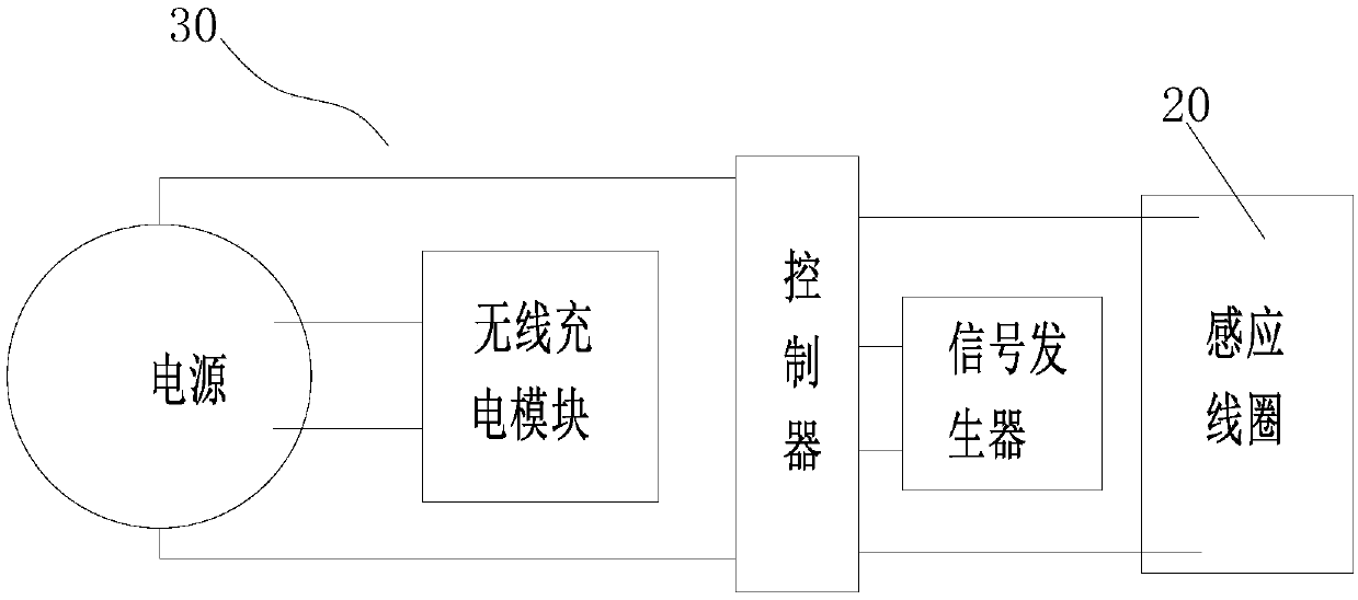
[0034] Such as figure 1 and figure 2 As shown, the artificial prosthesis of Embodiment 1 includes a prosthesis body 10 , an induction coil 20 and a detection circuit 30 . Wherein, the prosthesis body 10 forms a friction pair with the bone or other prosthesis, and the contact surface of the prosthesis body 10 and the bone or other prosthesis forms a friction surface. The induction coil 20 is arranged in the prosthesis body 10 , and there is a predetermined distance between the induction coil 20 and the friction surface of the prosthesis body 10 . The detection circuit 30 is arranged in the prosthesis body 10 and is connected to the induction coil 20. When the induction coil 20 is damaged, the detection circuit 30 can send out an alarm signal.
[0035] The prosthesis body 10 will wear on the friction surface as the use time increases. When the wear of the prosthesis body 10 reaches a certain level, the artificial prosthesis will have a negative impact on the patient and incre...
Embodiment 2
[0051] The artificial prosthesis of the second embodiment improves the arrangement of the induction coil 20, as Figure 6 As shown, the induction coils 20 of the second embodiment are reciprocatingly distributed in an S shape. Specific reference Figure 6 , the induction coils of the second embodiment are reciprocally arranged in the form of zigzag lines to cover the above-mentioned friction surface.
Embodiment 3
[0053] Such as Figure 7 to Figure 9 As shown, the artificial prosthesis of embodiment three is specifically a knee joint prosthesis, and the knee joint prosthesis of embodiment three mainly bears the force between the femur and the tibia, and its friction surface is as follows Figure 8 As shown, it is a curved surface facing upward, so the induction coil 20 is arranged under the friction surface according to the shape of the friction surface, and as shown Figure 9 shown over the entire friction surface. The force-bearing surface of the knee joint prosthesis of this embodiment is the upper and lower surfaces of the prosthesis, and the force-bearing direction is also along the vertical direction. Therefore, preferably, the accommodating recess 12 of this embodiment is arranged on the front side of the knee joint prosthesis, so as to The pressure on the electrical box 13 is reduced, and the wires of the induction coil 20 are arranged along the circumference of the prosthesis ...
PUM
 Abstract
Description
Claims
Application Information
 - R&D Engineer
- R&D Manager
- IP Professional
- Industry Leading Data Capabilities
- Powerful AI technology
- Patent DNA Extraction
Browse by: Latest US Patents, China's latest patents, Technical Efficacy Thesaurus, Application Domain, Technology Topic, Popular Technical Reports.
© 2024 PatSnap. All rights reserved.Legal|Privacy policy|Modern Slavery Act Transparency Statement|Sitemap|About US| Contact US: help@patsnap.com