
Shock-absorbing and anti-galling interphase spacers for transmission line conductors

A technology of interphase spacer and sub-conductor spacer, which is applied in the direction of the device for maintaining the distance between parallel conductors and the mechanical vibration attenuation device, etc., which can solve the problems of steplessly adjustable interphase spacer bracket or complex structure of connecting fittings, and achieve the weakening effect Force, avoid stress concentration, reduce wear effect

Active Publication Date: 2019-09-10
STATE GRID HENAN ELECTRIC ZHOUKOU POWER SUPPLY +1
View PDF11 Cites 0 Cited by
  • Summary
  • Abstract
  • Description
  • Claims
  • Application Information

AI Technical Summary

Problems solved by technology

[0009] The structure of the stepless adjustable interphase spacer bracket or connecting fittings mentioned above is relatively complex, and the structural length of the fittings needs to be adjusted by tightening multiple bolts during installation.

Method used


Image

  • Shock-absorbing and anti-galling interphase spacers for transmission line conductors
  • Shock-absorbing and anti-galling interphase spacers for transmission line conductors
  • Shock-absorbing and anti-galling interphase spacers for transmission line conductors

Examples


Embodiment 1

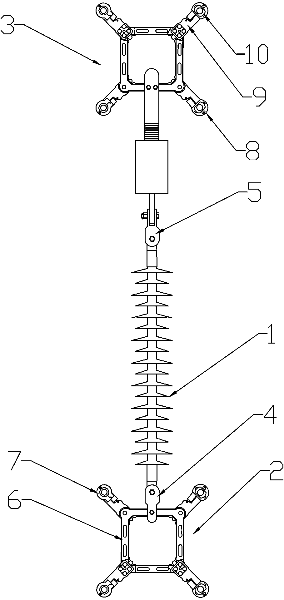
[0037] Such as figure 1 As shown, the shock-absorbing and anti-galling spacer between the wires of the transmission line includes a composite insulator 1, a sub-conductor spacer I2 and a sub-conductor spacer II3. The two ends of the composite insulator 1 are slot-shaped hole fittings, and the sub-conductor spacer I2 is hinged to the slot-shaped hole fitting at one end of the composite insulator 1 through a ZBD-type hanging plate 4, and the sub-conductor spacer II3 is hinged to the slot-shaped hole fitting at the other end of the composite insulator 1 through a right-angle hanging plate 5. An adjustable connection mechanism is connected between the right-angle hanging plate 5 and the sub-conductor spacer II3.

[0038] The sub-conductor spacer includes a spacer frame body 6, a rotary damping clamp 7 arranged on one side of the spacer frame body 6, and a fixed damper clamp arranged on the other side of the spacer frame body 6 8. Both the rotary damping clamp 7 and the fixed damp...

Embodiment 2

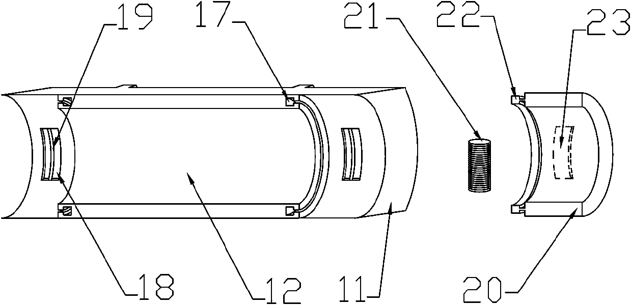
[0044] This embodiment is basically the same as the first embodiment, except that: the arc length of the T-shaped protrusion 22 is smaller than the arc length of the T-shaped sliding groove 17 .

Embodiment 3

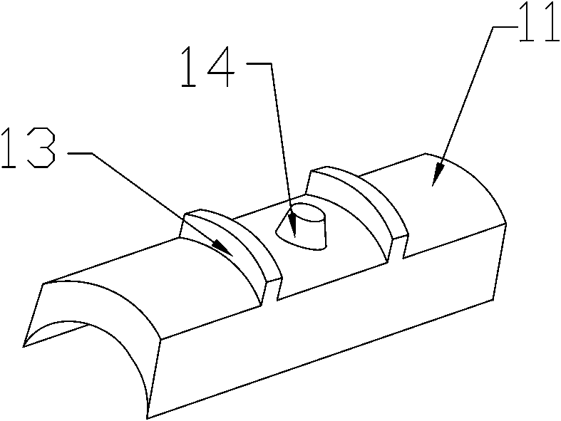
[0046] Such as Figure 4 , 7 As shown in -8, this embodiment is basically the same as the second embodiment, the difference is that: the frustum-shaped protrusion 14 is provided with a cylindrical fixing groove 37, and the inner wall of the fixing groove 37 is provided with a boss 38, the The upper surface of the boss 38 is arc-shaped, and the lower surface is vertical to the inner wall of the fixing groove 37. The T-shaped pin 39 is fixed in the said circular truncated through hole 16, and the pin shank diameter of the T-shaped pin 39 is larger than the said through hole. The pin shaft of the T-shaped pin 39 is placed in the fixed groove 37 through the frustum-shaped through hole 16, and the lower end of the pin shaft is a conical structure, and the pin shaft is provided with the boss 38. matching grooves.

[0047] During installation, the T-shaped pin 39 is fixed on the frustum-shaped through hole 16, and then the damping sleeve 10 is installed in the clamp body and the cl...


PUM


Abstract

The invention discloses a damping and gallop-preventing interphase spacer for a power transmission line wire. The damping and gallop-preventing interphase spacer comprises a composite insulator and sub wire spacers movably connected with the two ends of the composite insulator through fittings; an adjustable connecting mechanism is connected between the fittings and the sub wire spacers; each subwire spacer comprises a spacer frame and a rotary damping wire clamp and a fixed damping wire clamp arranged on the spacer frame; each fixed damping wire clamp comprises an outer wire clamp and an inner wire clamp arranged in the outer wire clamp; and each inner wire clamp comprises an inner wire clamp body and torsion damping parts arranged at the two ends of the inner wire clamp body. By virtueof the damping and gallop-preventing interphase spacer, the problem of easy stress concentration in the fixed damping wire clamp outlets can be solved effectively, so that abrasion to the wires and the wire clamps can be reduced; and by adoption of the adjustable connecting mechanism, the damping and gallop-preventing interphase spacer is simple in structure and easy to mount.

Description

technical field [0001] The invention relates to the field of overhead transmission lines in electric power systems, in particular to a shock-absorbing and gallop-proof interphase spacer for conductors of transmission lines. Background technique [0002] Due to the influence of wind, ice, low temperature and other meteorological conditions, the wires in the line often experience fatigue vibration in four directions: breeze vibration, sub-gap vibration, along-line vibration and galloping, which cause serious damage to the line. Flashovers and trips occur, and in severe cases, hardware and insulators are damaged, wire strands are broken, wires are broken, tower bolts are loosened, detached, and even towers are collapsed, resulting in major power grid accidents. Therefore, more and more shock-absorbing and anti-galling devices are used on the line, and interphase spacers are one of the most commonly used effective measures. [0003] At present, there are two main ways to fix th...

Claims


Application Information

Patent Timeline
Patent Type & Authority Patents(China)
IPC IPC(8): H02G7/12H02G7/14
Inventor 史宏伟韩庆军
Owner STATE GRID HENAN ELECTRIC ZHOUKOU POWER SUPPLY
Learn More