
Swing air-supplying type heat dissipation damping power distribution cabinet

A swinging air supply and heat dissipation technology, which is applied in the substation/power distribution device shell, anti-seismic equipment, cooling/ventilation of substation/switchgear, etc. Problems such as the influence of components in the power distribution cabinet, to achieve good shock absorption and buffering effects, good shock absorption effects, and accelerated heat loss

Inactive Publication Date: 2018-01-16
合肥名龙电子科技有限公司
View PDF0 Cites 12 Cited by
  • Summary
  • Abstract
  • Description
  • Claims
  • Application Information

AI Technical Summary

Problems solved by technology

[0003] Existing power distribution cabinets generally have a number of heat dissipation holes on the end surface of the top plate. The heat dissipation holes lead to poor gas fluidity and often lead to slow heat dissipation, so that the heat of the power distribution cabinet is always in a state of accumulation. The internal components of the power distribution cabinet will be affected, and the electronic components inside the power distribution cabinet will produce certain vibrations during the operation and use of the power distribution cabinet, while the traditional power distribution cabinet cannot play a good shock absorption and buffering effect , affecting the service life of the distribution cabinet

Method used


Image

  • Swing air-supplying type heat dissipation damping power distribution cabinet
  • Swing air-supplying type heat dissipation damping power distribution cabinet
  • Swing air-supplying type heat dissipation damping power distribution cabinet

Examples


Embodiment Construction

[0021] The following will clearly and completely describe the technical solutions in the embodiments of the present invention with reference to the accompanying drawings in the embodiments of the present invention. Obviously, the described embodiments are only some, not all, embodiments of the present invention. Based on the embodiments of the present invention, all other embodiments obtained by persons of ordinary skill in the art without making creative efforts belong to the protection scope of the present invention.

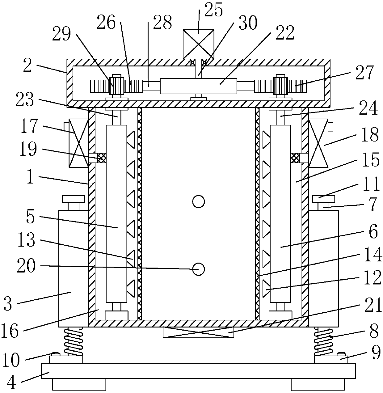
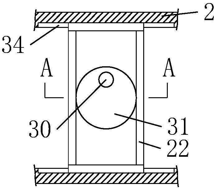
[0022] see Figure 1-5 , in an embodiment of the present invention, a swinging air-supply heat dissipation type shock-absorbing power distribution cabinet includes a cabinet body 1, a transmission box 2, a support sleeve 3, a base 4, an air supply pipe 5, an exhaust pipe 6, and a blower 17 , Exhaust fan 18, swing sleeve 22, No. 1 tooth plate 26 and No. 2 tooth plate 27, two partitions 14 are arranged symmetrically in the inner cavity of the cabinet body 1, and...


PUM


Abstract

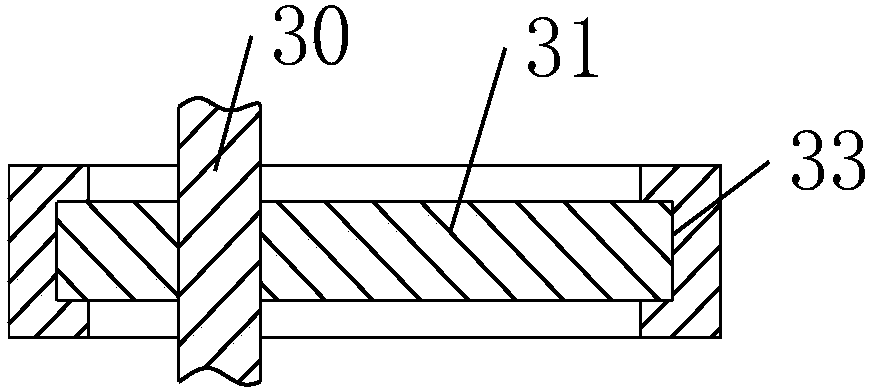
The invention discloses a swing air-supplying type heat dissipation damping power distribution cabinet. The power distribution cabinet comprises a cabinet body, a transmission box, a supporting sleeve, a base, an air-supplying pipe, an air-exhausting pipe, an air blower, an exhaust blower, a swing sleeve, a number one toothed plate and a number two toothed plate; the air-supplying pipe is fixedlyerected at the bottom of a number one rotary rod; the air-exhausting pipe is fixedly erected at the bottom of a number two rotary rod; a rotary shaft is rotationally arranged in the middle part of aninner cavity of the transmission box; an eccentric wheel is fixedly mounted on the outer ring of the rotary shaft; the swing sleeve is glidingly arranged on the eccentric wheel in a sleeving manner; push-pull rods are symmetrically and fixedly welded on the two sides of the swing sleeve; the number one toothed plate is fixedly mounted on the end part of the push-pull rod on the left side of the swing sleeve; the number two toothed plate is fixedly mounted on the end part of the push-pull rod on the right side of the swing sleeve; and annular gears are fixedly mounted at the top ends of the number one rotary rod and the number two rotary rod respectively. The power distribution cabinet is simple in structure, reasonable in design, good in heat dissipation effect, high in damping and buffering effect and suitable for popularization and use.

Description

technical field [0001] The invention relates to the technical field of power distribution cabinets, in particular to a vibration-absorbing power distribution cabinet of a swinging air-supply heat dissipation type. Background technique [0002] The power distribution cabinet is a cabinet made of steel to protect the normal operation of components. The production materials of power distribution cabinets are generally divided into two types: hot-rolled steel plates and cold-rolled steel plates. Compared with hot-rolled steel sheets, cold-rolled steel sheets are softer and more suitable for the production of power distribution cabinets. Power distribution cabinets are widely used mainly in chemical industry, environmental protection industry, power system, metallurgical system, industry, nuclear power industry, fire safety monitoring, transportation industry and so on. [0003] Existing power distribution cabinets generally have a number of heat dissipation holes on the end su...

Claims


Application Information

Patent Timeline
IPC IPC(8): H02B1/56H02B1/54H02B1/30
Inventor 黄思宜
Owner 合肥名龙电子科技有限公司
Learn More