
A Broadband Dielectric Loaded Gyro TWT High Frequency System

A medium-loaded, traveling-wave tube technology, applied in the direction of the coupling device of the transit-time electronic tube, can solve the problems of low output power and the inability of the medium-loaded structure to meet the high power output of wide-band work at the same time, and achieve high linear gain, Guaranteed wide-band operating characteristics and the effect of achieving stable operation

Active Publication Date: 2019-07-19
四川杰诺创科技有限公司
View PDF2 Cites 0 Cited by
  • Summary
  • Abstract
  • Description
  • Claims
  • Application Information

AI Technical Summary

Problems solved by technology

[0005] The present invention proposes a medium-loaded wide-band cyclotron TWT high-frequency system, which solves the problem that the existing medium-loaded structure cannot simultaneously satisfy wide-band work and higher power output
At the same time, the gradual change of the output structure is adopted to solve the problem of low output power caused by low gain at high frequency points, so that the high frequency system of the cyclotron traveling wave tube can not only meet the requirements of wide frequency band work, but also provide higher microwave power within the frequency band. power output

Method used


Image

  • A Broadband Dielectric Loaded Gyro TWT High Frequency System
  • A Broadband Dielectric Loaded Gyro TWT High Frequency System
  • A Broadband Dielectric Loaded Gyro TWT High Frequency System

Examples


Embodiment Construction

[0023] The present invention will be further described in detail below with reference to the Ka-band design example and the accompanying drawings. It should be noted that the invention is not limited to this example.

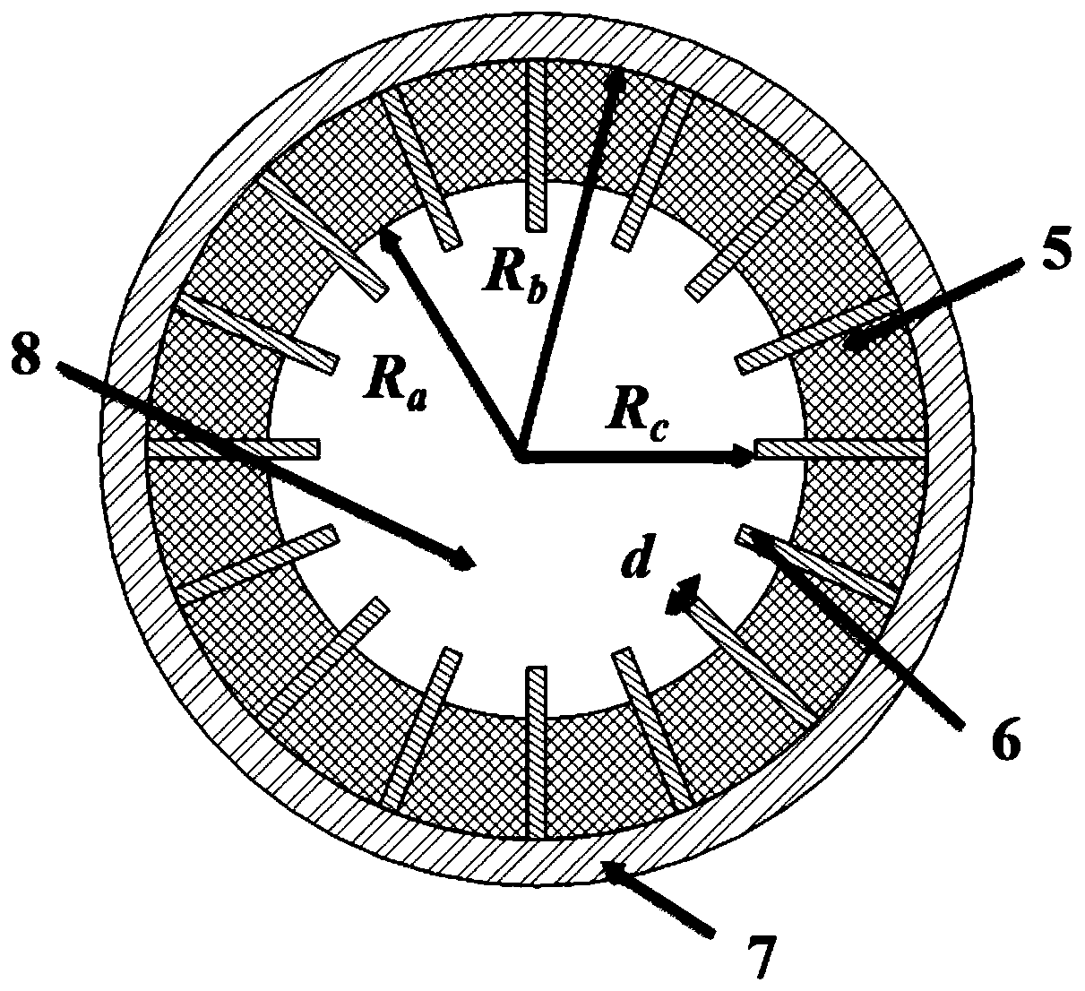
[0024] attached figure 1 , 2 3 and 3 respectively give the three-dimensional structure diagram, axial section diagram and transverse section diagram of the high frequency system of broadband dielectric loaded gyrotraveling wave tube provided by this implementation example. The broadband medium-loaded high-frequency system in the present invention includes a pre-grouping section 1 , a linear amplification section 2 , a nonlinear amplification section 3 , and an output gradient section 4 . The pre-grouping section, the linear amplification section, the nonlinear amplification section, and the output gradual change section include a metal circular waveguide shell, and the inner wall of the circular waveguide is loaded with a ring-shaped non-destructive medium-load...


PUM


Abstract

The invention discloses a novel wideband dielectric loaded gyro traveling wave tube high frequency system, and belongs to the technical field of microwave, millimeter wave and terahertz devices. The system comprises pre-bunching section, a linear amplification section, a nonlinear amplification section and an output gradual change section which are sequentially connected, and is characterized in that the pre-bunching section, the linear amplification section, the nonlinear amplification section and the output gradual change section comprise a metal circular waveguide shell and an annular lossless dielectric loading waveguide which is loaded in a mode of attaching to the circular waveguide inner wall, the linear amplification section is uniformly provided with rectangular lossy dielectric pieces in the angular direction, and the lossy dielectric pieces are distributed in a periodic manner along the axial direction. Dispersion characteristics of the whole high frequency structure are changed through loading the lossless dielectric waveguide, an electron beam curve and a waveguide dispersion curve are enabled to meet resonance conditions within a wide frequency band range, and wideband operating characteristics are ensured; and meanwhile, a gradually changing output structure is adopted, so that a problem of low output power brought about by low gain of a high frequency point is solved. The system disclosed by the invention not only can meet wideband operating requirements, but also can provide high microwave power output within the frequency band range.

Description

technical field [0001] The invention belongs to the technical field of microwave, millimeter wave and terahertz devices, and specifically relates to a high-frequency system of a broadband medium-loaded gyrotraveling wave tube, which can be applied to gyrotraveling wave tubes in the millimeter wave and terahertz bands. Background technique [0002] The cyclotron traveling wave tube is a microwave amplifier based on the electronic cyclotron maser effect. It has the ability to generate broadband, high-power, and high-efficiency electromagnetic wave output in the microwave, millimeter wave, and even terahertz frequency bands. It is widely used in microwave communications. systems, millimeter wave countermeasures, millimeter wave imaging systems, etc. At present, the gyrotron traveling wave tube is in a stage of rapid development, and increasing the output power and expanding the frequency bandwidth are the two main development directions. [0003] The interaction structure of t...

Claims


Application Information

Patent Timeline
Patent Type & Authority Patents(China)
IPC IPC(8): H01J23/36
Inventor 王建勋李昊姚叶雷商亚粉罗勇
Owner 四川杰诺创科技有限公司
Learn More