Charging system

A charging system and charging pile technology, which is applied in the direction of electric vehicles, electric traction, vehicle energy storage, etc., can solve the problems of idle charging piles, single layout scheme, and increased parking lot engineering costs, so as to reduce manufacturing costs and facilitate selection Effect

Pending Publication Date: 2018-01-16
OPTIMUM BATTERY CO LTD
View PDF0 Cites 5 Cited by
  • Summary
  • Abstract
  • Description
  • Claims
  • Application Information

AI Technical Summary

Problems solved by technology

[0003] At present, the layout of charging piles in the parking lot is relatively simple. One charging pile is configured for each parking space. When the parking space is occupied by other non-charging vehicles, a large number of charging piles will be idle, which will lead to a waste of resources.
[0004] In addition, the functions of the existing charging piles are either DC charging (fast charging) or AC charging (slow train), and it is impossible to realize the random deployment of DC charging or AC charging for a certain parking space, thereby limiting the user's choice
For example, if a user of a parking space equipped with an AC charging pile wants to perform DC charging, he must change the parking space, which is inconvenient for the user to operate; if each parking space is to be equipped with an AC charging pile and a DC charging pile to facilitate the user's choice, It is necessary to build a lot of new charging piles, which will increase the engineering cost of the parking lot

Method used


Image

  • Charging system
  • Charging system
  • Charging system

Examples


Embodiment Construction

[0012] In order to make the object, technical solution and beneficial technical effects of the present invention clearer, the present invention will be further described in detail below in conjunction with the accompanying drawings and specific embodiments. It should be understood that the specific implementations described in this specification are only for explaining the present invention, not for limiting the present invention.

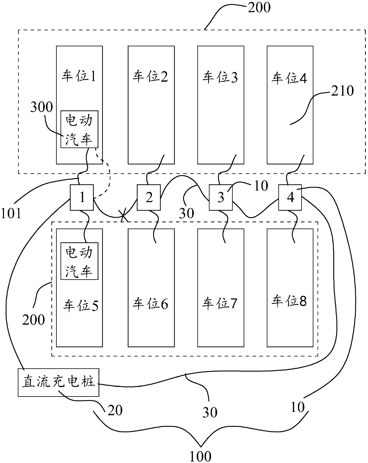
[0013] see figure 1 , which is an application schematic diagram of the charging system 100 provided in the embodiment of the present invention. The charging system is applied in a parking lot, and the parking lot includes at least one row of parking spaces 200 , wherein the at least one row of parking spaces 200 includes a plurality of individual parking spaces 210 arranged side by side. The charging system 100 includes a plurality of relay charging piles 10 and at least one DC charging pile 20 . The multiple relay charging piles 10 correspond to...


PUM


Abstract

The invention provides a charging system which is applied to a parking lot. The parking lot comprises at least a row of parking spaces, wherein the parking spaces comprise multiple single parking spaces which are arranged side by side. The charging system comprises multiple relay charging piles and at least one direct-current charging pile used for providing a direct-current charging function, wherein the multiple relay charging piles are in one-to-one correspondence with the multiple single parking spaces, every two adjacent relay charging piles in the multiple relay charging piles are connected with each other, and the relay charging pile located at the head end and the relay charging pile located at the tail end are each connected with one direct-current charging pile; and each relay charging pile comprises at least one alternating-current charging gun so as to conduct alternating-current charging on an electric automobile, and one relay charging pile in every two adjacent relay charging piles is disconnected with the other relay charging pile and connected with the electric automobile so as to conduct direct-current charging on the electric automobile. According to the chargingsystem, double choices of direct-current charging or alternating-current charging can be achieved at each parking space, and the cost is low.

Description

【Technical field】 [0001] The invention relates to the technical field of charging equipment for electric vehicles, in particular to a charging system. 【Background technique】 [0002] The function of the charging pile is similar to the refueling machine in the gas station. It can be fixed on the ground or wall, and installed in public buildings (public buildings, shopping malls, public parking lots, etc.) and residential area parking lots or charging stations. Charge all models of electric vehicles. [0003] At present, the layout of charging piles in the parking lot is relatively simple. One charging pile is equipped with one parking space. When the parking space is occupied by other non-charging vehicles, a large number of charging piles will be idle, which will lead to a waste of resources. [0004] In addition, the functions of the existing charging piles are either DC charging (fast charging) or AC charging (slow train), and it is impossible to realize the random deploy...

Claims


Application Information

Patent Timeline
Patent Type & Authority Applications(China)
IPC IPC(8): B60L11/18E04H6/42
CPCY02T10/70
Inventor 薛哲峰谢世杰陈军
Owner OPTIMUM BATTERY CO LTD
Why Eureka
Try Eureka