In-built structure of wheel hub

A technology of built-in and hub, applied in the field of vehicles, can solve the problems of increased rotational inertia of the hub, increased unsprung mass of the car, and low motor efficiency, and achieves the effects of weight reduction, low heat generation, and high motor efficiency.

Pending Publication Date: 2018-01-12
浙江万安智驱科技有限公司
View PDF1 Cites 4 Cited by
  • Summary
  • Abstract
  • Description
  • Claims
  • Application Information

AI Technical Summary

Problems solved by technology

Since the in-wheel motor technology integrates the power device, transmission device and braking device into the wheel hub, in order to meet the driving performance of the vehicle, the torque of the in-wheel motor usually has high requirements. The volume and weight of the traditional in-wheel motor are increasing The increase of the torque increases significantly, resulting in a large increase in the unsprung mass of the car, excessive space occupation of the wheel hub, and a corresponding increase in the moment of inertia of the wheel hub, which affects the main control performance of the car such as acceleration, braking, and steering. At the same time, the motor The calorific value also increases, and the requirements for the motor heat dissipation performance are more stringent
[0003] Chinese Patent Application Publication No. CN 105529848 U, dated 2016.04.27, titled "Electric Wheel Hub Motor and Electric Vehicle Wheel", discloses a motor with at least two turns of permanent magnets on the rotor and radially spaced permanent magnets. The hub motor can obtain stronger driving force, but the winding of this hub motor has end loss, the efficiency of the motor is not high, the winding space and the magnetic circuit space are mutually restricted, the heat generation is not reduced, and it is difficult to break through the bottleneck of the traditional hub motor

Method used


Image

  • In-built structure of wheel hub
  • In-built structure of wheel hub
  • In-built structure of wheel hub

Examples


Embodiment Construction

[0025] The present invention will be further described below in conjunction with the accompanying drawings and specific embodiments.

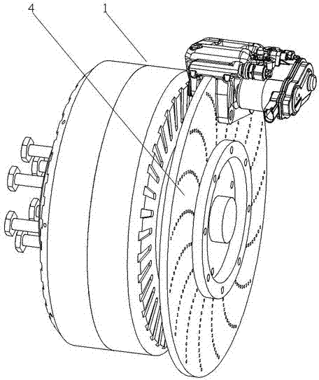
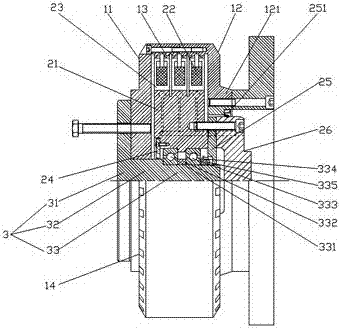
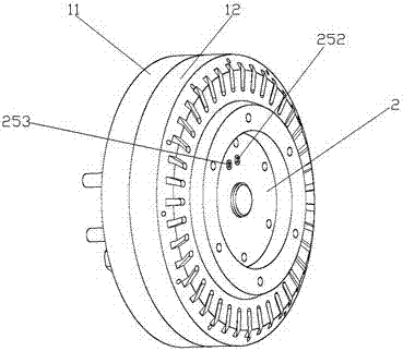
[0026] like Figure 1 to Figure 5 As shown in , a hub built-in structure, including

[0027] Motor and brake disc 4. The motor includes a rotor 1, a stator 2, and a rotating shaft 3. The stator is located in the rotor. The rotor is formed by connecting the first rotor 11 and the second rotor 12. The rotating shaft is fixed by the connecting shaft 31, the supporting shaft 32 and the stator. The shafts 33 are connected sequentially, the first rotor is provided with a positioning hole, the connecting shaft is connected with the first rotor, the supporting shaft passes through the positioning hole, the fixed shaft of the stator is connected with the stator in rotation, and the brake disc is connected with the rotor; the stator includes a stator bracket 21 and a number of iron core groups, the iron core group includes windings 22 and several U-shap...


PUM


Abstract

The invention discloses and provides an in-built structure, which has a light structure and good heat dispersion performance under the same torque, of a wheel hub. The in-built structure comprises a motor and a brake disc, wherein the motor comprises a rotor, a stator and a revolving shaft, the stator is arranged in the rotor, the revolving shaft is connected with the rotor, the revolving shaft isrotationally connected with the stator, and the braking disc is connected with the rotor; the stator comprises a stator support and a plurality of iron core sets, the iron core sets comprise a plurality of U-shaped iron cores and line sets, the U-shaped iron cores are provided with wire wrapping grooves, the line sets pass through all the wire wrapping grooves, the rotor is provided with a plurality of magnets, each U-shaped iron core is corresponding to two magnets, and the magnetic poles of two adjacent iron cores are opposite. The in-built structure has the beneficial effects that under the same torque, the structure is light, and the weight is reduced accordingly as well; all coils are used for generating torque, the thermal loss is less, the motor efficiency is high, and the corresponding calorific value is less as well; the in-built structure has a multi-fold heat radiation structure and a good heat dissipation effect; the end face cover plate and the rotor are sealed, thereby being able to prevent water and dust effectively.

Description

technical field [0001] The invention relates to the field of vehicles, in particular to a hub interior structure. Background technique [0002] Most of the new energy vehicles are driven by electricity, and the in-wheel motor technology has significant advantages such as omitting a large number of transmission components, making the vehicle structure simpler, high transmission efficiency, and independently driving a single wheel. Therefore, the in-wheel motor technology has a broad application in the field of new energy vehicles. Application prospect. Since the in-wheel motor technology integrates the power device, transmission device and braking device into the wheel hub, in order to meet the driving performance of the vehicle, the torque of the in-wheel motor usually has high requirements. The volume and weight of the traditional in-wheel motor are increasing The increase of the torque increases significantly, resulting in a large increase in the unsprung mass of the car,...

Claims


Application Information

Patent Timeline
Patent Type & Authority Applications(China)
IPC IPC(8): H02K1/16H02K1/27H02K3/28H02K7/08H02K5/16H02K5/10H02K1/20H02K1/32H02K7/102
Inventor 陈锋马志敏李璐吴作柱汤充
Owner 浙江万安智驱科技有限公司
Why Eureka
Try Eureka