Stripping device for hot extruding die

A mold and red punching technology, applied in the field of red punching die punching device, can solve the problems of product surface bumping and punching efficiency, high temperature of processed parts, easy sticking of punches, etc., saving labor, improving economic benefits, and reducing risks The effect of the probability of the situation

Active Publication Date: 2018-01-12
日照市方进金属制品有限公司
View PDF5 Cites 3 Cited by
  • Summary
  • Abstract
  • Description
  • Claims
  • Application Information

AI Technical Summary

Problems solved by technology

[0003] The mechanical properties of red punching parts are good. After red punching, the metal blank is heated, extruded and cooled, and its metal structure changes, which eliminates the original defects caused by casting or drawing, so that the internal crystal structure of the part is from the inside to the outside. The linear shape improves the mechanical properties of red punched parts. During the stamping process of red punched bonnet and nut-like blanks and blanks that are difficult to demould, the product is easy to stick to the punch, resulting in product backflushing and The two products are superimposed and stamped, resulting in damage to the punching machine and safety problems of product splashing. When the worker finds out, he must knock the product with a tool to demould, resulting in scratches on the product surface and low stamping efficiency. In addition, the temperature of the processed part after demoulding is high , the operator still has a certain risk when collecting

Method used


Image

  • Stripping device for hot extruding die
  • Stripping device for hot extruding die
  • Stripping device for hot extruding die

Examples


Embodiment Construction

[0021] The following will clearly and completely describe the technical solutions in the embodiments of the present invention with reference to the accompanying drawings in the embodiments of the present invention. Obviously, the described embodiments are only some, not all, embodiments of the present invention. Based on the embodiments of the present invention, all other embodiments obtained by persons of ordinary skill in the art without making creative efforts belong to the protection scope of the present invention.

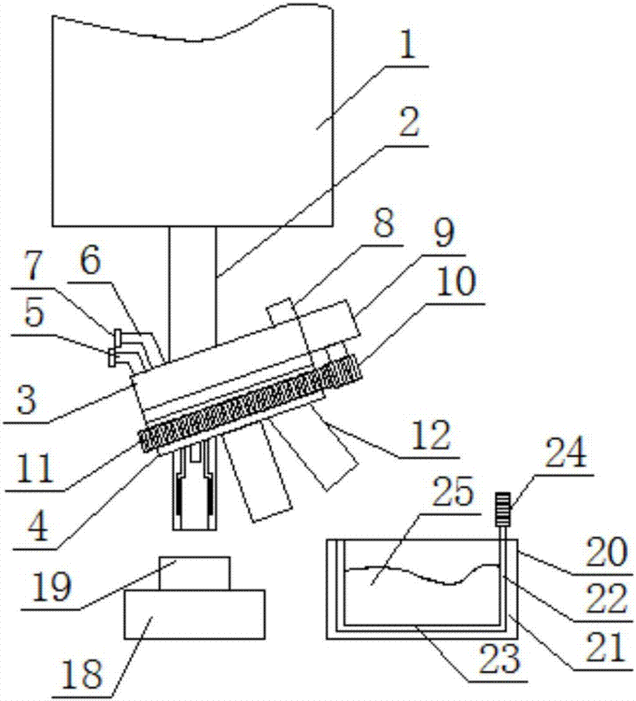
[0022] according to figure 1 As shown in a red punching die feeding device, the bottom of the body 1 is provided with a straight rod 2, the bottom of the straight rod 2 is provided with an upper conversion body 3, and the bottom of the upper conversion body 3 is provided with a lower conversion body 4, The upper conversion main body 3 and the lower conversion main body 4 are flexibly connected by a rotating shaft, so that the motor 9 can drive the lower conver...


PUM


Abstract

The invention discloses a stripping device for a hot extruding die. The stripping device comprises a machine body, wherein a straight rod is arranged at the bottom of the machine body; an upper conversion body is arranged at the bottom of the straight rod; a lower conversion body is arranged at the bottom of the upper conversion body; an air inlet pipe and a water inlet pipe are arranged at one end of the upper conversion body, and a controller is arranged at the other end of the upper conversion body; the air inlet pipe is arranged on one side of the water inlet pipe; a gas solenoid valve isarranged on the air inlet pipe; a liquid solenoid valve is arranged on the water inlet pipe; a threaded connector is arranged at the end part of each of the air inlet pipe and the water inlet pipe; amotor is arranged on the side surface of the upper conversion body; a gear is arranged at the end part of the motor; a gear ring is arranged on the outer side of the lower conversion body; a punchinghead is arranged at the bottom of the lower conversion body; the punching head comprises a punching head body; and a gas nozzle is arranged at the top of the inner cavity of the punching head body. According to the stripping device for the hot extruding die, through the arrangement of the upper conversion body and the lower conversion body, the demolding is facilitated, the manpower is saved, theworking efficiency is improved, and economic benefits are greatly improved.

Description

technical field [0001] The invention relates to the technical field of punch parts, in particular to a punching device for a red punch die. Background technique [0002] Red stamping die is a process for metal materials to be formed by heated stamping. During processing, the heated metal blank is first put into the mold, and it is plastically deformed in the mold cavity by the stamping of the press, thereby pressing out various shapes and shapes. Pressed parts with good mechanical properties. [0003] The mechanical properties of red punching parts are good. After red punching, the metal blank is heated, extruded and cooled, and its metal structure changes, which eliminates the original defects caused by casting or drawing, so that the internal crystal structure of the part is from the inside to the outside. The linear shape improves the mechanical properties of red punched parts. During the stamping process of red punched bonnet and nut-like blanks and blanks that are diff...

Claims


Application Information

Patent Timeline
IPC IPC(8): B21D37/16B21D45/02
Inventor 黄浩
Owner 日照市方进金属制品有限公司
Why Eureka
Try Eureka