
Power device and power feedback circuit thereof

A power supply equipment and feedback circuit technology, applied in the power supply field, can solve problems such as dangerous economy, poor connection, loss, etc., and achieve the effects of ensuring normal operation, stable input voltage, and fast processing speed

Active Publication Date: 2018-01-09
GUANGDONG OPPO MOBILE TELECOMM CORP LTD
View PDF3 Cites 2 Cited by
  • Summary
  • Abstract
  • Description
  • Claims
  • Application Information

AI Technical Summary

Problems solved by technology

[0003] If the connection between the feedback voltage signal line and the feedback network of the power supply module is poor, or not connected, or wrongly connected, the voltage at the voltage output port of the power supply device will continue to rise until the voltage at the voltage output port of the power supply device is equal to the voltage of the power supply. The maximum output voltage of
This voltage is input to the load-side equipment through wires, causing the load-side equipment to work abnormally or even burn the load-side equipment, causing danger and economic losses
[0004] In addition, many application loads do not have high requirements on the power supply and do not require accurate input voltage. Therefore, there is no interface reserved at the power supply input end to connect to the power module feedback network, and the power feedback circuit of related technologies cannot be used, which affects production efficiency. and cost input

Method used


Image

  • Power device and power feedback circuit thereof
  • Power device and power feedback circuit thereof

Examples


Embodiment Construction

[0026] Embodiments of the present invention are described in detail below, examples of which are shown in the drawings, wherein the same or similar reference numerals designate the same or similar elements or elements having the same or similar functions throughout. The embodiments described below by referring to the figures are exemplary and are intended to explain the present invention and should not be construed as limiting the present invention.

[0027] The power supply device and its power supply feedback circuit according to the embodiments of the present invention will be described below with reference to the accompanying drawings.

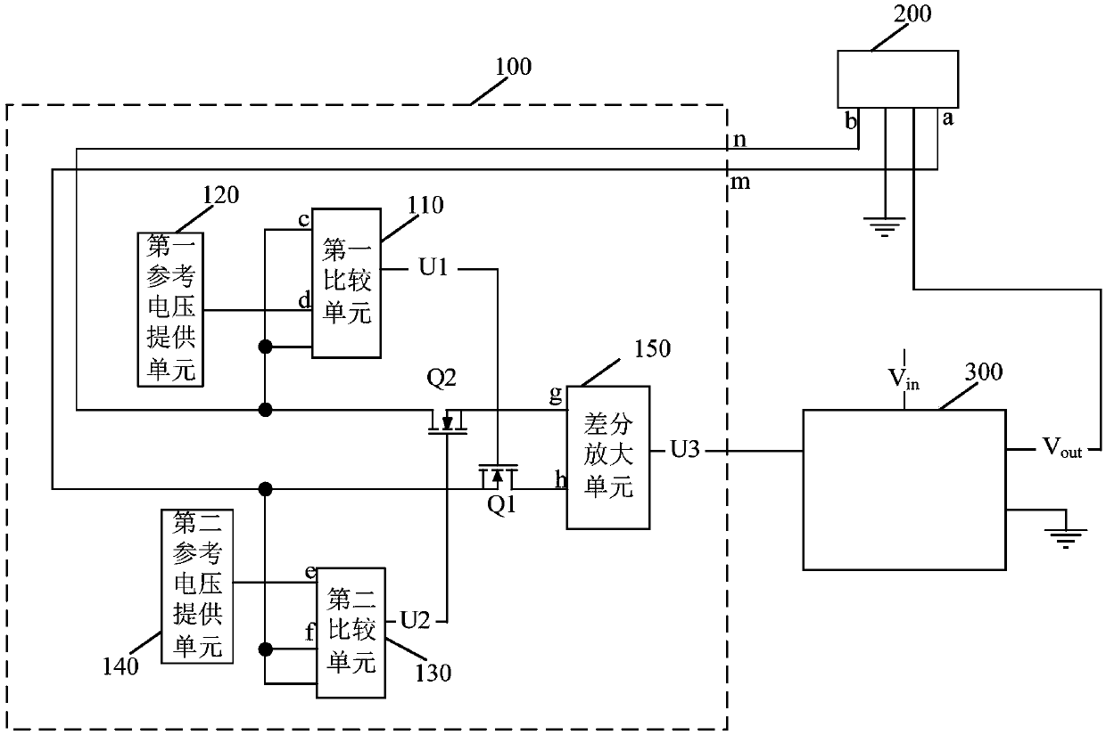
[0028] figure 1 It is a schematic structural diagram of a power feedback circuit of a power supply device according to an embodiment of the present invention.

[0029] Such as figure 1As shown, the power feedback circuit 100 of the power supply device according to the embodiment of the present invention includes: a first voltage feedback...


PUM


Abstract

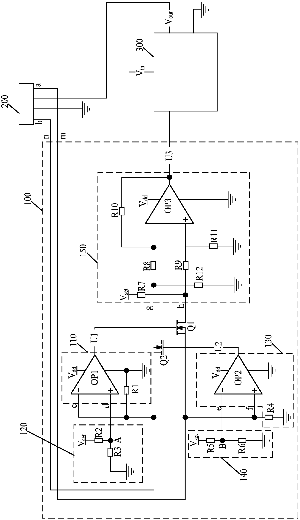
The invention discloses a power device and a power feedback circuit thereof. The circuit comprises a first voltage feedback end and a second voltage feedback end that are used for correspondingly connecting with a positive feedback pin and a negative feedback pin in a power connection port of the power device, a first comparison unit used for outputting a first comparison signal according to a voltage fed back by the second voltage feedback end and a first reference voltage provided by a first reference voltage providing unit, so as to control on and off of a second switch transistor, a secondcomparison unit used for outputting a second comparison signal according to a voltage fed back by the first voltage feedback end and a second reference voltage provided by a second reference voltageproviding unit, so as to control on and off of a first switch transistor, and a differential amplification unit used for outputting a feedback voltage to a voltage adjustment unit of the power deviceaccording to on and off states of the first switch transistor and the second switch transistor, wherein the voltage adjustment unit adjusts an output voltage according to the feedback voltage, so as to enable the output voltage of the power connection port to meet the requirement of a load end device.

Description

technical field [0001] The invention relates to the technical field of power supplies, in particular to a power feedback circuit of a power supply device and a power supply device. Background technique [0002] In related technologies, there are mainly two schemes for the design of the power supply feedback circuit: one is near-end feedback, that is, the feedback voltage signal is directly extracted from the voltage output port of the voltage supply device, and the feedback voltage signal is input to the power module feedback network; the other is It is remote feedback, that is, the lead wire from the voltage input port of the load device, and the feedback voltage signal is connected to the power feedback network from the voltage output port of the voltage supply device. The above two solutions require that the feedback voltage signal line and the power module feedback network are in a good connection state, and no missing or wrong connections are allowed. [0003] If the c...

Claims


Application Information

Patent Timeline
IPC IPC(8): H02M1/00
Inventor 杨波
Owner GUANGDONG OPPO MOBILE TELECOMM CORP LTD
Learn More