Distillation column used for solvent recovery

A distillation tower and solvent technology, applied in the field of solvent recovery distillation towers, can solve the problems of fast rising speed, influence, and low recovery efficiency, and achieve the effect of slowing the rising speed, ensuring the distillation effect, and ensuring the continuity.

Inactive Publication Date: 2018-01-09
重庆天穗环保科技有限公司
View PDF2 Cites 3 Cited by
  • Summary
  • Abstract
  • Description
  • Claims
  • Application Information

AI Technical Summary

Problems solved by technology

[0003] Solvent recovery often requires the use of distillation equipment for separation and purification. However, the existing distillation equipment has some defects. During the distillation process, the vaporized liquid rises quickly in the distillation tower, and there is no effective barrier on the way to make it rise. If the speed is too fast, the contact between the gas and the liquid is insufficient, the interphase mass transfer cannot be carried out effectively, and the expected distillation effect cannot be achieved, which will adversely affect the quality of the product.
At the same time, after the distillation has been carried out for a period of time, the waste solvent that has been purified by distillation must be discharged from the distillation device, and then the new waste solvent to be recovered is recycled and added to the distillation device. The operation is troublesome, and the recovery process is not continuous, resulting in low recovery efficiency.

Method used


Image

  • Distillation column used for solvent recovery
  • Distillation column used for solvent recovery

Examples


Embodiment 1

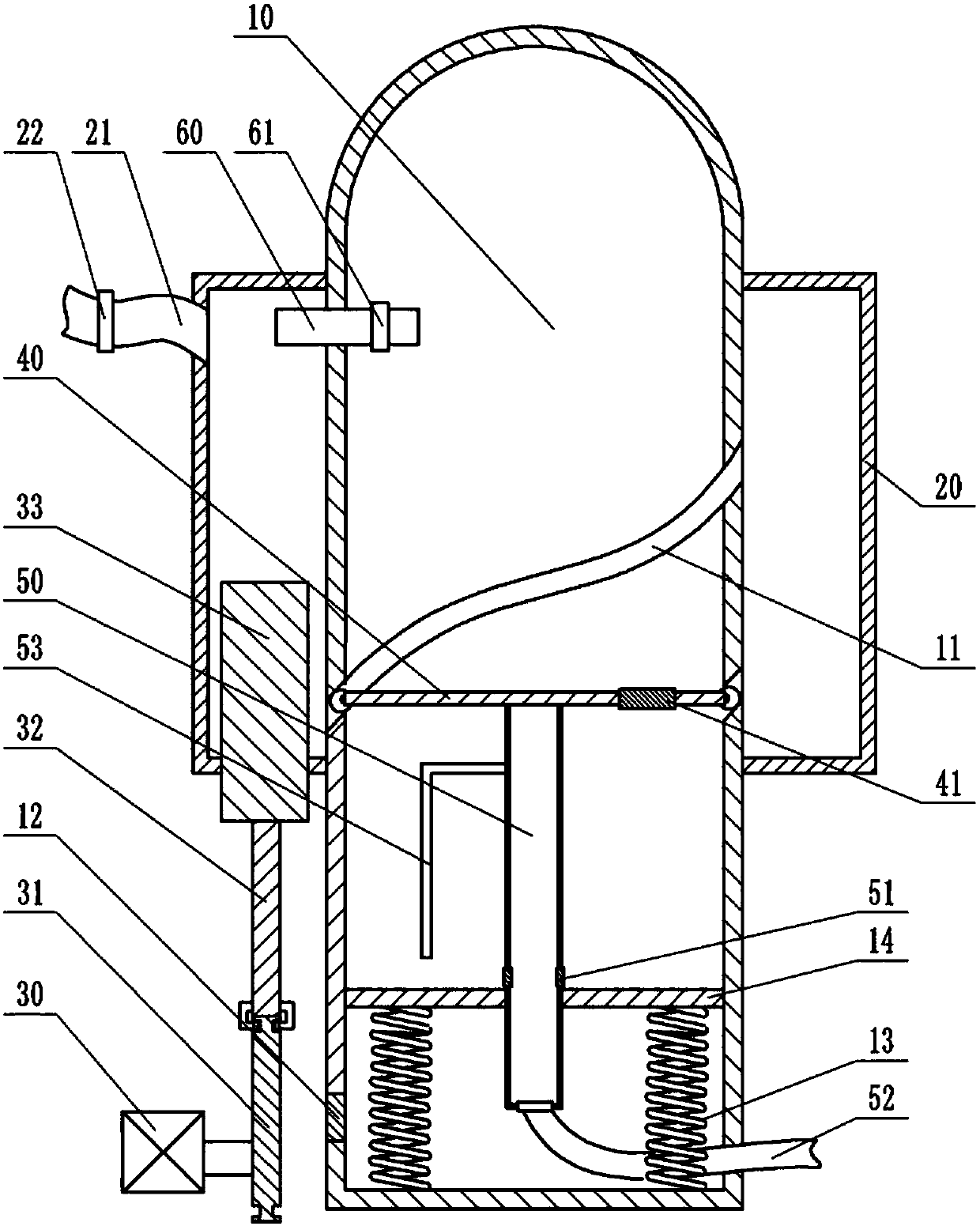
[0024] like figure 1As shown, a rectification device for recovering organic solvents includes a power unit, a distillation tank 10 and a baffle 40 , and the baffle 40 is located in the distillation tank 10 . The lower part of the retort 10 is slidably connected with a partition 14, and a plurality of springs 13 are connected between the partition 14 and the inner wall of the retort 10. The plurality of springs 13 are evenly distributed along the circumference of the partition 14, and the springs 13 are arranged on the partition. The plate 14 has a supporting effect, and when the substance on the dividing plate 14 increases, the spring 13 is compressed, and the dividing plate 14 slides down along the inner wall of the retort 10 . The retort 10 is provided with a one-way door 12 located below the partition 14 , and when the one-way door 12 is squeezed by the liquid in the retort 10 , the one-way door 12 can be opened toward the outside of the retort 10 . The inner wall of the m...

Embodiment 2

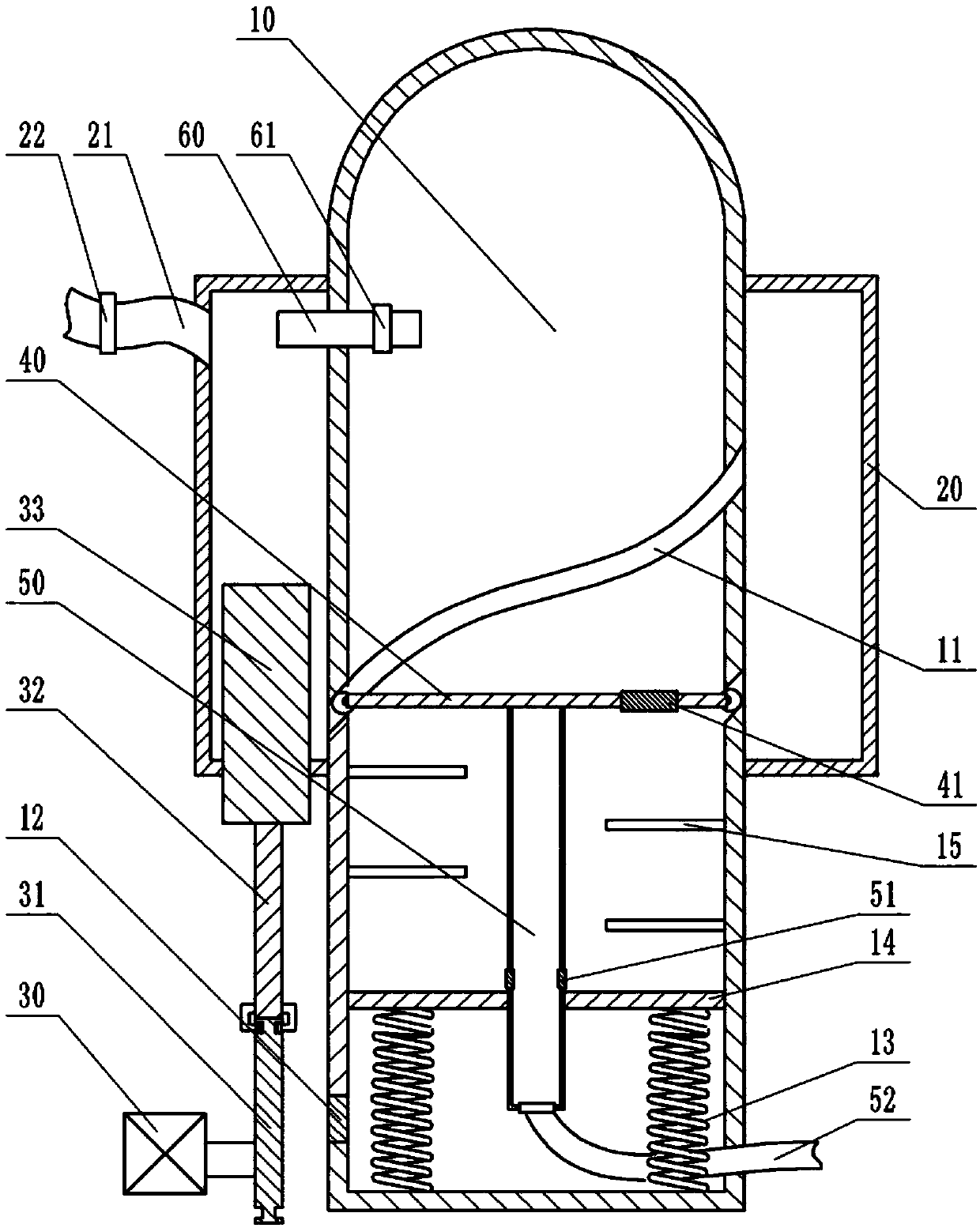
[0027] The difference between this embodiment and embodiment 1 is: as figure 2 As shown, the stirring shaft 53 is not provided on the side wall of the steam pipe 50 ; a plurality of slow flow plates 15 located below the grooves 11 are alternately provided on the inner wall of the distillation tank 10 . The slow flow plates 15 are arranged alternately to form a gas and liquid circulation channel in the distillation tank 10. The heating vapor at the bottom of the distillation tank 10 moves upward along the circulation channel, and the waste solvent falling on the baffle plate 40 flows to the partition along the circulation channel. 14. The setting of the circulation channel increases the movement stroke of the heating steam and the waste solvent, slows down the flow velocity of the heating steam and the reflux liquid, enables the two phases of the vapor and liquid to fully contact for interphase mass transfer, and improves the effect of distillation.


PUM


Abstract

The invention belongs to the technical field of solvent recovery, and more specifically discloses a distillation column used for solvent recovery. The distillation column used for solvent recovery comprises a distillation tank, a power unit, and a spoiler; a separating plate is slidingly arranged in the lower part of the distillation tank; springs are arranged between the separating plate and theinternal wall of the distillation tank; the distillation tank is provided with a single-way door below the separating plate; the internal wall at the middle part of the distillation tank is provided with a plurality of spiral grooves; the spoiler is connected with rolling balls via hinge joint; a pressure valve is arranged on the spoiler; a steam pipe is fixedly arranged on the lower surface of the spoiler; the side wall of the steam pipe is provided with a first single-way valve; the lower end of the steam pipe is connected with a corrugated pipe through a universal joint; the side wall of the distillation tank is provided with a material storage sandwich layer; a feed pipe is arranged in the material storage sandwich layer; a second single-way valve is arranged on the feed pipe; the power unit is used for driving waste solvent in the material storage sandwich layer to move into the distillation tank through the feed pipe. The distillation column is used for solvent recovery, is capable of reducing gas rising speed, ensuring distillation effect, and increasing product quality.

Description

technical field [0001] The invention belongs to the technical field of solvent recovery, in particular to a distillation tower for solvent recovery. Background technique [0002] A large amount of waste solvents will be produced in industrial production, and direct discharge of these waste solvents will pollute the environment, so these waste solvents are usually treated before discharge. Some solvents in waste solvents can be recycled, and the recovered solvents can be reused in industrial production, saving resources and reducing production costs of enterprises. Solvent recovery usually uses the principle of distillation. The solvent to be recovered is turned into a gaseous state by heating and distillation, and the vapor enters the cooling system to liquefy and flow out, so that clean solvent is recovered. Through solvent recovery, waste, dirty and old solvents can be regenerated and recycled, which can not only save a lot of procurement costs, but also reduce environmen...

Claims


Application Information

Patent Timeline
Patent Type & Authority Applications(China)
IPC IPC(8): B01D3/00
Inventor 张瑜阳杨林辉荣毛小英汪小飞殷地利杨帆贺雪峰
Owner 重庆天穗环保科技有限公司
Why Eureka
Try Eureka