
Drilling leakage zone position recognition system

A technology for identifying system and leakage, applied in earth-moving drilling, wellbore/well components, measurement, etc., can solve the problems of cumbersome, complicated construction, increase well control risk, etc., to reduce the link of reading data and reduce tripping Drilling time, effect of reducing well control risk

Pending Publication Date: 2018-01-05
中石化石油工程技术服务有限公司 +2
View PDF5 Cites 0 Cited by
  • Summary
  • Abstract
  • Description
  • Claims
  • Application Information

AI Technical Summary

Problems solved by technology

However, there are still some problems in these methods. For example, the cable or drill pipe is used to measure after lost circulation, which has certain risks. For example, the collapse of the well wall can easily cause pipe sticking accidents, and the construction is also relatively complicated; It is necessary to perform tripping operations after leakage occurs, and then run into the instrument for measurement
This not only increases the risk of well control, but also makes the construction complicated and cumbersome

Method used


Image

  • Drilling leakage zone position recognition system
  • Drilling leakage zone position recognition system

Examples


Embodiment Construction

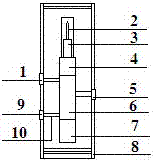
[0016] to combine figure 1 , figure 2 The implementation process of the present invention will be described. The leakage measurement nipple consists of a magnetic field antenna 2, a radio frequency signal reader 3, a data storage cabin 4, an instrument circuit cabin 6, a battery cabin 7, an insulating support rod 10, a flow sensor 5, a temperature sensor 9, a pressure sensor 1 and an outer tube short Section 8 is composed. The magnetic field antenna 2 is connected with the radio frequency signal reader 3 through a data transmission line. Outer cylinder nipple 8 is made of drill collar, grooves are carved on the outer wall, flow sensor 5, temperature sensor 9, pressure sensor 1 are installed, holes are drilled through the circuit, and sealed with sealing plugs. Insulating support rods 10 are respectively installed at the openings of the inner wall of the short joint 8 of the outer cylinder, and circuits are installed inside the insulating support rods 10. One end of the cir...


PUM


Abstract

The invention provides a drilling leakage zone position recognition system, which can be used for judging the accurate leakage occurring position. An externally embedded measuring pup joint is used; by measuring three parameters of the pressure, the flow rate and the temperature of an annular space, the drilling fluid leakage occurring position is measured and comprehensively analyzed, so that theleakage zone position is accurately obtained; and through a radio frequency technology, stored data is fast read. The instrument is arranged in a position near a drilling bit in a pup joint form; theleakage parameters are recorded and stored; then, a radio frequency tag is used for reading the data; and the read data are processed and analyzed on the ground. The technology has small influence onthe drilling construction; and the well control risk is favorably reduced.

Description

technical field [0001] The invention relates to an instrument for petroleum drilling, in particular to an instrument for measuring leakage layers. Background technique [0002] During oil and gas drilling, lost circulation is usually a complex and thorny problem. After the leakage occurs, it is necessary to accurately determine the location of the leakage layer as soon as possible, so as to take effective plugging measures in time and ensure the normal drilling. my country began to develop leakage measurement instruments in the 1970s. Most of these instruments were developed with the help of the principle of fluid dynamics. It either converts the fluid flow when the leakage occurs into the displacement of the diaphragm for measurement, or uses the turbine flowmeter to measure Principle for flow measurement. Only in recent years has the technology of using multiple methods to complement each other to measure the missing position, and the accuracy has been greatly improved. ...

Claims


Application Information

Patent Timeline
Patent Type & Authority Applications(China)
IPC IPC(8): E21B47/10E21B47/06E21B47/07E21B47/00E21B47/12E21B47/26
Inventor 刘振东王传富李公让赵金海明玉广高杨刘国亮
Owner 中石化石油工程技术服务有限公司
Learn More