
House frame

A frame and house technology, applied in construction, building construction, etc., can solve the problems of limited load-bearing capacity and limited load-bearing capacity of house frames, and achieve the effect of saving assembly time and improving construction efficiency.

Pending Publication Date: 2018-01-05
张引强
View PDF5 Cites 3 Cited by
  • Summary
  • Abstract
  • Description
  • Claims
  • Application Information

AI Technical Summary

Problems solved by technology

However, the load-bearing capacity of the steel structure itself is limited, especially when the beam is connected to the steel column through the connector. When the beam is subjected to a large vertical pressure, the pressure will concentrate on the welding position of the connector and the steel column. The welding area of ​​the column is relatively fragile and there is a greater risk of fracture, which results in a limited load-bearing capacity of the steel structure house frame

Method used


Image

  • House frame
  • House frame
  • House frame

Examples


no. 1 example

[0048] The house frame includes a single-layer frame, and the house frame includes a one-layer or at least two-layer single-layer frame. The single-layer frame includes columns and beams, and the beams and columns are connected to form the entire single-layer frame.

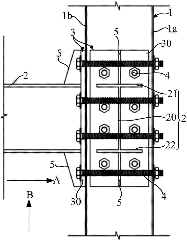
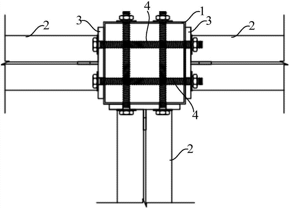
[0049] refer to figure 1 , the column 1 and the beam 2 are connected through the first connecting piece 3 , and the first connecting piece 3 and the column 1 are connected with the bolt 4 .

[0050] The first connecting piece 3 and the column 1 are connected by bolts 4 , and there is no welding area between the column 1 and the first connecting piece 3 . When the crossbeam 2 is subjected to relatively large pressure in the vertical direction, the bolts 4 connecting the first connecting piece 3 and the column 1 can bear relatively large pressure without breaking easily, which can improve the load-bearing capacity of the building frame.

[0051] Bolt 4 can be selected from high-strength bolts, which have higher s...

no. 2 example

[0062] Compared with the first embodiment, the difference of the second embodiment is:

[0063] refer to Figure 5 and combine Image 6 The first connector 13 includes a plate portion 130 and an extension portion 131 extending from the plate portion 130 toward the beam 12. The plate portion 130 and the column 11 are connected by bolts (hereinafter referred to as first bolts 14), and the extension portion 131 is connected to the beam 12. 12 are also connected by bolts (hereinafter referred to as second bolts 16).

[0064] The first bolt 14 only passes through the side wall 11 a of the column 11 and the plate portion 130 and the plate portion 130 , and the first bolt 14 does not pass through the side wall 11 b of the column 11 opposite to the side wall 11 a. refer to Image 6 and combine Figure 7 , the side wall 11a of the column 11 and the plate portion 130 are provided with through holes and aligned. Taking the through hole 130a provided on the plate portion 130 as an ex...

no. 3 example

[0082] Compared with the second embodiment, the third embodiment differs in that:

[0083] refer to Figure 11 , the beam 22 is a square beam, and the corresponding ends of the square beam along the length direction are accommodated in the groove 230 of the first connecting member 23 . An operation window 220 is provided in the top wall of the crossbeam 22 , through the operation window 220 , a second bolt 26 is installed to connect the sidewall of the crossbeam 22 and the groove wall of the groove 230 . After the frame of the house is assembled, concrete can be filled in the square beams at the construction site to enhance the strength of the house.

[0084] As an improvement, the operating window can be arranged in the bottom wall of the beam. Thus, operating windows may be provided in the top and / or bottom wall of the beam.


PUM


Abstract

A house frame comprises a single-layer frame, the single-layer frame comprises vertical columns and cross beams which are connected through first connecting pieces, and the first connecting pieces andthe vertical columns are connected through bolts; and / or the house frame comprises at least two single-layer frames, all the single-layer frames are stacked in the height directions of the vertical columns, every two vertical columns oppositely arranged in the height directions of the vertical columns are connected through a second connecting piece, and the second connecting pieces and the corresponding two vertical columns are connected through bolts. According to the technical scheme, the first connecting pieces and the vertical columns are connected through the bolts, and no welding area exists between the vertical columns and the first connecting pieces; when the cross beams are subjected to the high pressure in the vertical direction, the bolts connecting the first connecting pieceswith the vertical columns can bear the high pressure and are not likely to be fractured so that the load-bearing capacity of the house frame can be improved; and the multi-layer house frame can also be assembled in a factory and then transported to a construction site, thus large-scale production of the multi-layer house frame can be achieved, and the house construction efficiency is greatly improved.

Description

technical field [0001] The invention relates to the technical field of construction, in particular to a house frame. Background technique [0002] In the construction engineering industry, the housing frame is usually realized in the following two forms: [0003] The first form is a reinforced concrete house frame. The columns and beams in the house frame are all made by adding steel mesh to the concrete. The steel mesh connects the concrete into a whole and has a large load-bearing capacity. However, the preparation process of the reinforced concrete structure is completed on the construction site, and the process is complicated, which requires high construction personnel. [0004] The second form is a steel structure house frame, which includes steel columns welded with connectors on the outer surface and beams connected to the steel columns through the connectors. Compared with the first housing frame form, the second housing frame form can save assembly time. However,...

Claims


Application Information

Patent Timeline
Patent Type & Authority Applications(China)
IPC IPC(8): E04B1/24E04B1/58
Inventor 张引强
Owner 张引强
Learn More