
An injection mold placement rack

A technology for injection molds and racks, applied in tool storage devices, manufacturing tools, etc., can solve the problems of troublesome picking and placing and single placing function, and achieve the effects of convenient picking and placing of molds, high storage efficiency, and solving troublesome picking and placing

Active Publication Date: 2019-06-11
大连福赛汽车部件有限公司
View PDF3 Cites 0 Cited by
  • Summary
  • Abstract
  • Description
  • Claims
  • Application Information

AI Technical Summary

Problems solved by technology

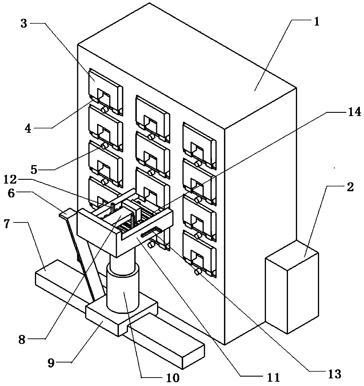
[0003] According to the deficiencies of the prior art above, the technical problem to be solved by the present invention is to propose an injection mold placement frame, which places the molds in the placement holes of the frame body sequentially through a lifting device, and a baffle plate is provided in front of the placement holes to prevent the mold from Sliding down, at the same time, the turning device on the lifting frame can easily stand up the mold, which solves the troublesome problem of single placement of traditional mold placement functions, and has the characteristics of high storage efficiency, convenient and safe mold placement

Method used


Image

  • An injection mold placement rack
  • An injection mold placement rack
  • An injection mold placement rack

Examples


Embodiment Construction

[0013] Referring to the accompanying drawings, through the description of the embodiments, the specific embodiments of the present invention include the shape, structure, mutual position and connection relationship of each part, the function and working principle of each part, and the manufacturing process of the various components involved. And the method of operation and use, etc., are described in further detail to help those skilled in the art have a more complete, accurate and in-depth understanding of the inventive concepts and technical solutions of the present invention.

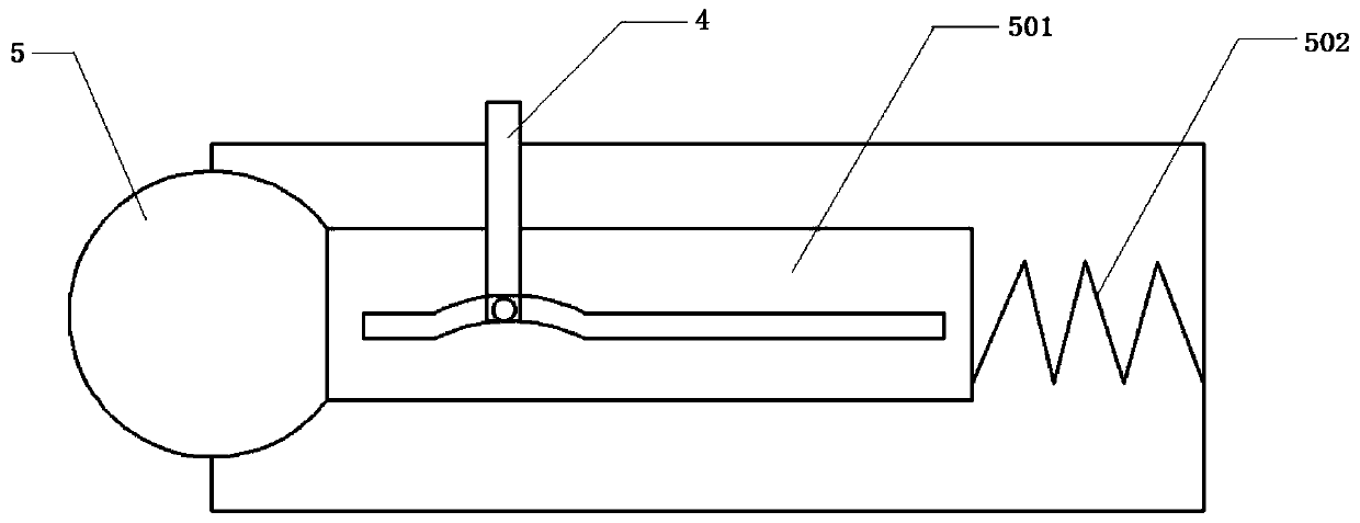
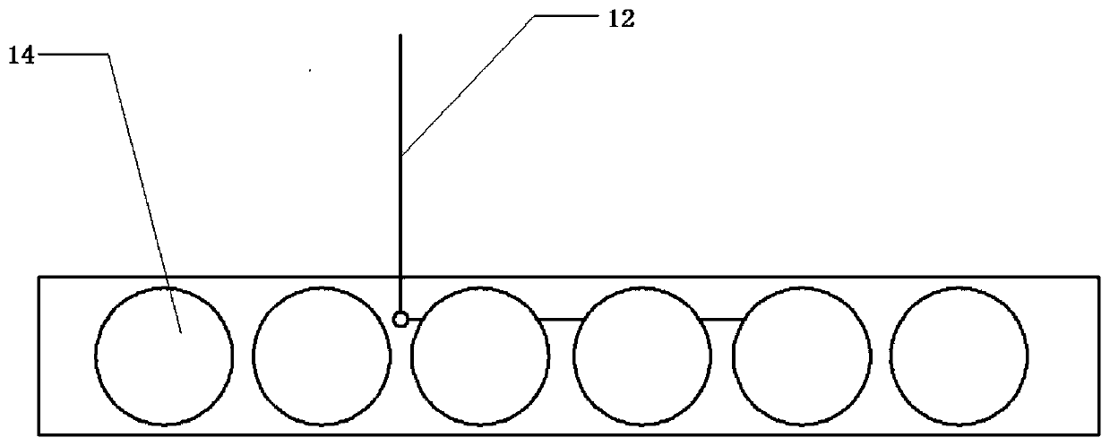
[0014] Such as Figure 1-4 As shown, an injection mold placement frame includes a frame body 1, a push-off device, a guide roller 14, a guide wheel, a lifting platform, a controller and a blocking door. The frame body 1 is a rectangular structure, and the front of the frame body 1 is provided with Several placement holes for placing injection molds, the placement holes are rectangular holes, and the ...


PUM


Abstract

The invention discloses an injection mould storing frame comprising a frame body, pushing devices, guide rollers, guiding wheels, a lifting placing table and blocking doors. The frame body is of a rectangular structure; a plurality of storing holes used for storing injection moulds are formed in the front face of the frame body, are rectangular and are horizontally formed in the front side face ofthe frame body; the lifting placing table used for lifting and pushing the injection moulds is fixed to the position, in front of the frame body, of the ground; the storing holes face the lifting placing table; the pushing devices comprise the first pushing device and the second pushing device; the first pushing device is perpendicularly arranged at the bottom of the storing holes; the second pushing device is arranged on the lifting placing table; the multiple guide rollers are arranged on the lower side face of the storing holes in a horizontally-rotating mode; the guide rollers and the front side face of the frame body are horizontal; the guiding wheels are arranged on the two side faces of the storing holes; and the blocking doors covering the storing holes are arranged in the front of the storing holes. The moulds can be conveniently stored and safely erected according to the requirement, and the injection mould storing frame has the characteristics of being compact in structure,convenient and efficient.

Description

technical field [0001] The invention belongs to the technical field of mechanical equipment, and in particular relates to an injection mold placing frame. Background technique [0002] Molds are various molds and tools used in industrial production for injection molding, blow molding, extrusion, die-casting or forging forming, smelting, stamping and other methods to obtain the required products. Under the action of external force, the blank becomes a tool with a specific shape and size. Widely used in blanking, die forging, cold heading, extrusion, powder metallurgy parts pressing, pressure casting, and compression molding or injection molding of engineering plastics, rubber, ceramics and other products. The mold is a precision tool with a complex shape and bears the expansion force of the billet. It has high requirements for structural strength, rigidity, surface hardness, surface roughness and machining accuracy. However, the weight of the mold is large, which is easy to...

Claims


Application Information

Patent Timeline
Patent Type & Authority Patents(China)
IPC IPC(8): B29C45/17B25H3/04
Inventor 殷敖金金乐海代璧辉谭小川焦文胜
Owner 大连福赛汽车部件有限公司
Learn More