Protection Devices and Fuse Devices
A technology for protection devices and fuses, which is applied in emergency protection devices, electrical components, circuits, etc., and can solve problems such as abnormal drop in output voltage
- Summary
- Abstract
- Description
- Claims
- Application Information
AI Technical Summary
Problems solved by technology
Method used
Image
Examples
Deformed example 1
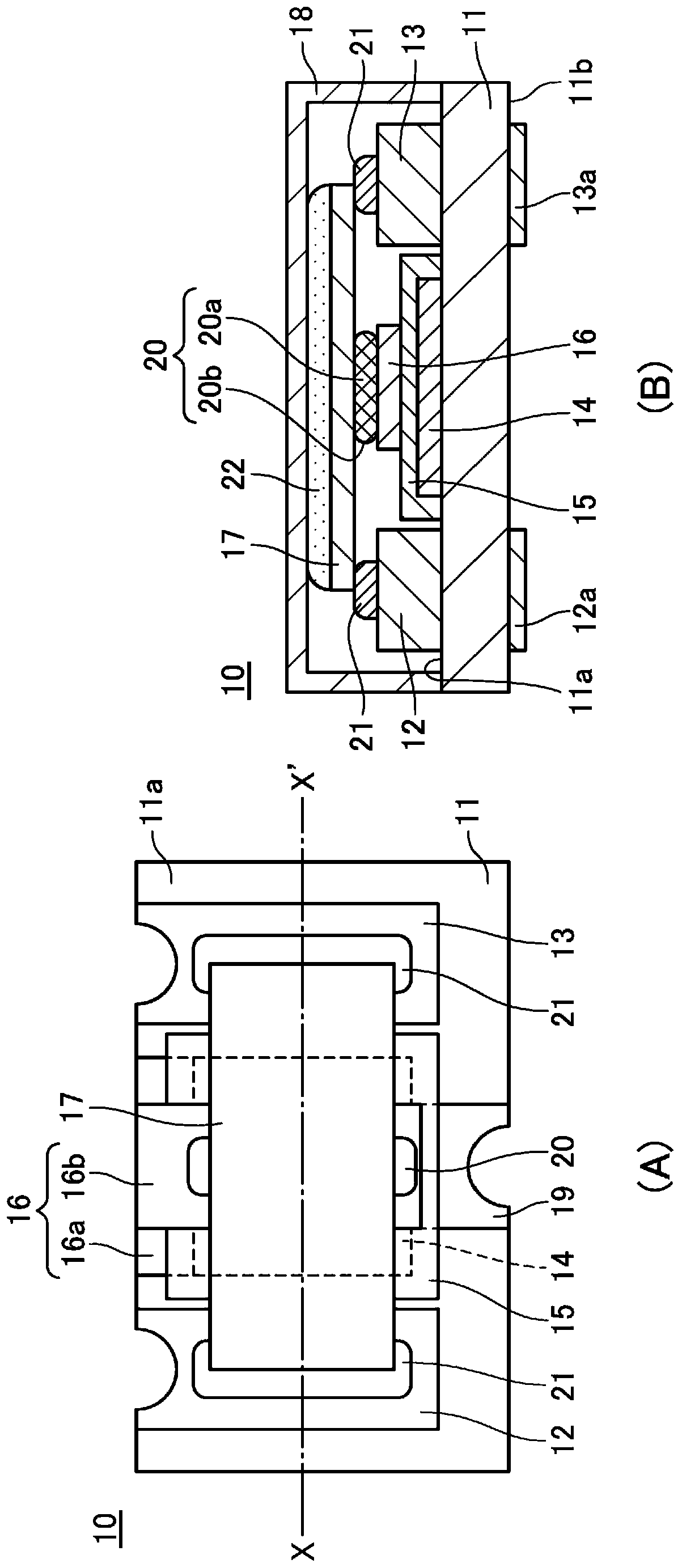
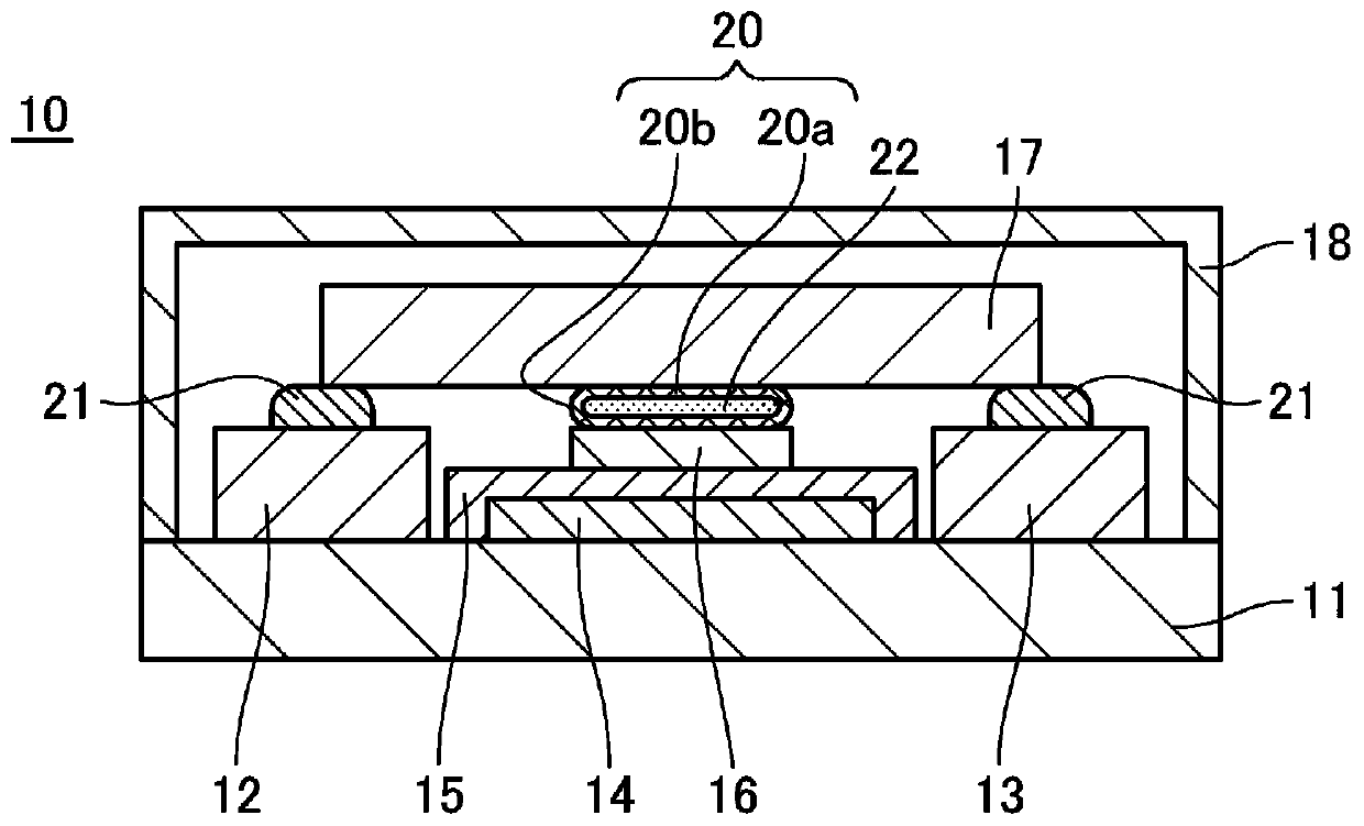
[0081] It should be noted that, figure 1 In the protection device 10 shown in , only the elastic member 20 is provided on the lead-out electrode 16 of the heating element to support the fuse element 17, but it can also be as Figure 4 As shown, the elastic member 20 is provided on the first electrode 12 and the second electrode 13 , and the connecting solder 21 is provided on the heating element lead-out electrode 16 . Figure 4 The protection device 30 shown can absorb and relax the stress between the first electrode 12 and the heating element lead-out electrode 16 through the elastic member 20 provided on the first electrode 12, and the elastic member provided on the second electrode 13 20, the stress between the second electrode 13 and the heating element lead-out electrode 16 can be absorbed and relaxed.
[0082] It should be noted that the protective device 30 may also be formed on the back surface 11 b of the insulating substrate 11 by the heating element 14 as describ...
Deformed example 2
[0084] In addition, if Figure 6 As shown, in the protection device, the elastic member 20 having the conductive layer 20b formed of a bonding material such as solder may be provided on the first electrode 12, the second electrode 13, and the heating element lead-out electrode 16. Figure 6 In the protection device 40 shown, the fuse element 17 is bonded to the first electrode 12, the second electrode 13, and the heating element lead-out electrode 16 through the conductive layer 20b of the elastic member 20, thereby achieving electrical conduction. also, Figure 6 The protective device 40 shown absorbs and relaxes the stress between the fuse element 17 and the device frame through the elastic members 20 provided on the first electrode 12 , the second electrode 13 and the heating element lead-out electrode 16 .
Deformed example 3
[0086] In addition, if Figure 7 As shown, the protective device can also be provided with an elastic member 20 on the insulating layer 15 . Figure 7 In the shown protection device 50 , the fuse element 17 is bonded to the first electrode 12 , the second electrode 13 , and the heating element lead-out electrode 16 via the solder 21 for connection, and electrical conduction is achieved. Furthermore, in the protection device 50 , the elastic member 20 provided on the insulating layer 15 is connected to the fuse portion 17 a between the first electrode 12 and the heating element extraction electrode 16 and between the second electrode 13 and the heating element extraction electrode 16 . The fusing part 17a of the fuse element 17 refers to the fusing part in the fuse element 17 connected between the heating element lead-out electrode 16 and the first electrode 12 and the second electrode 13, specifically, refers to the heating element lead-out electrode. 16 and the first electro...
PUM
 Abstract
Description
Claims
Application Information
 - R&D Engineer
- R&D Manager
- IP Professional
- Industry Leading Data Capabilities
- Powerful AI technology
- Patent DNA Extraction
Browse by: Latest US Patents, China's latest patents, Technical Efficacy Thesaurus, Application Domain, Technology Topic, Popular Technical Reports.
© 2024 PatSnap. All rights reserved.Legal|Privacy policy|Modern Slavery Act Transparency Statement|Sitemap|About US| Contact US: help@patsnap.com


