Current detection device

A current detection device and current path technology, applied in the direction of measurement device, measurement current/voltage, resistor installation/support, etc., to prevent the current detection accuracy from deteriorating

Inactive Publication Date: 2018-01-02
KOA CORP
View PDF7 Cites 0 Cited by
  • Summary
  • Abstract
  • Description
  • Claims
  • Application Information

AI Technical Summary

Problems solved by technology

[0004] However, in such a method of connecting a bus bar and a shunt resistor, since the number of connected parts increases, it becomes a main cause of heat generation due to contact resistance, and there are problems in ensuring connection reliability.

Method used


Image

  • Current detection device
  • Current detection device
  • Current detection device

Examples


Embodiment Construction

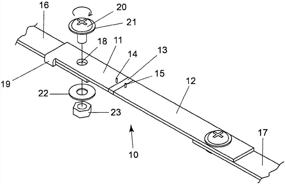
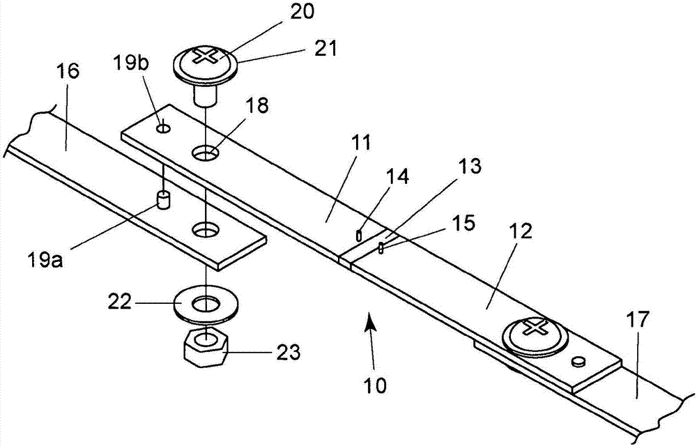
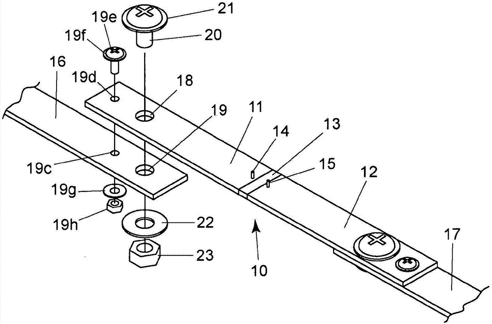
[0021] Below, refer to Figure 1 to Figure 9 , the embodiment of the present invention will be described. In addition, in each figure, the same or corresponding member or element is attached|subjected and demonstrated the same code|symbol.

[0022] figure 1 A shunt-type current detection device according to Embodiment 1 of the present invention is shown. This device includes: a long strip-shaped first wiring member 11 and a second wiring member 12 made of Cu, Cu-based alloy, Al, etc. a highly conductive metal material; and a resistor 13 made of a metal material with a lower temperature coefficient of resistance than the wiring member and bonded to the first wiring member and the second wiring member. The elongated first wiring member 11 and the second wiring member 12 are bus bars serving as current paths, and are also terminal pieces joined to the resistors 13 . The length and shape of the first wiring member 11 and the second wiring member 12 may be the same or differen...


PUM


Abstract

Provided is a current detection device that is configured such that, when using a fixing member to fix a bus bar, which is a current path, by rotation to a current detection device configured as a shunt resistor, a load is not applied to a surface to be joined with the resistor. The invention is provided with a first wiring member (11) and second wiring member (12), which comprise a conductive metal material, and a resistor (13), which comprises a metal material having a lower temperature coefficient of resistance than said wiring members and is joined to the first wiring member and second wiring member, wherein the first wiring member is provided with a through-hole portion (18), into which a fixing member (20) for rotational fixing is inserted, and a positioning portion (19), which serves to prevent rotation of the first wiring member caused by the rotational fixing of fixing members (20, 23).

Description

technical field [0001] The present invention relates to a current detection device for measuring current flowing through a bus bar, and more particularly, to a shunt type current detection device capable of performing high-precision current measurement while using a bus bar as a current wiring. Background technique [0002] It is measured by using a shunt resistor in the detection of the charge and discharge current of the storage battery, the detection of the current of the motor driving the electric vehicle or the hybrid vehicle, the detection of the current of the electric equipment such as an air conditioner, or the power generation equipment such as a solar battery, etc. The current is detected by the potential difference generated by the energization of the resistor. [0003] In particular, there are cases where a bus bar is used as a path for supplying current from a power source such as a storage battery to various electric devices, and a shunt resistor is connected ...

Claims


Application Information

Patent Timeline
Patent Type & Authority Applications(China)
IPC IPC(8): G01R15/00H01C3/00H01C13/00
CPCH01C1/01H01C1/14H01C7/00G01R31/364G01R1/203G01R19/16542Y02E60/10H01M10/48G01R15/146H01C3/00H01C13/02H01C17/28H01M10/425H01R11/287
Inventor 仲村圭史雨宫仁志蓑轮宏一
Owner KOA CORP
Why Eureka
Try Eureka