
Vehicular air-conditioning apparatus

An air-conditioning device and vehicle technology, applied in air-conditioning systems, vehicle components, applications, etc., can solve problems such as air enlargement, suction inlet noise, flow path resistance increase, etc., and achieve the effect of compact structure and noise suppression

Active Publication Date: 2018-01-02
DENSO CORP
View PDF8 Cites 6 Cited by
  • Summary
  • Abstract
  • Description
  • Claims
  • Application Information

AI Technical Summary

Problems solved by technology

However, in the case where the direction is a direction intersecting the rotation axis of the centrifugal fan, the flow velocity of the air may become large locally at the suction port of the centrifugal fan.
As a result, there are disadvantages such as noise at the suction port and increased flow path resistance.

Method used


Image

  • Vehicular air-conditioning apparatus
  • Vehicular air-conditioning apparatus
  • Vehicular air-conditioning apparatus

Examples


Embodiment Construction

[0023] Below, while referring to the attached Figure 1 Embodiments of the present invention will be described. In order to make the description easier to understand, in each of the drawings, the same reference numerals are assigned to the same constituent elements as much as possible, and overlapping descriptions are omitted.

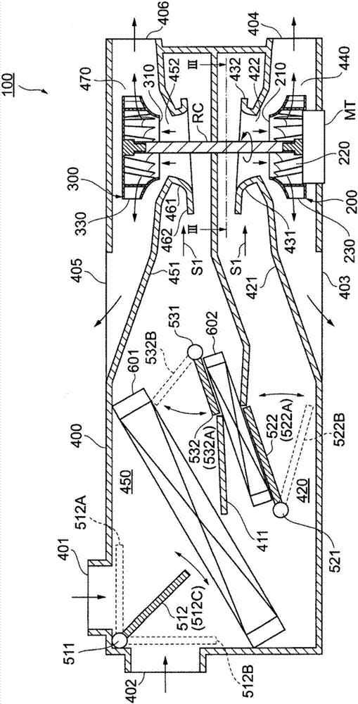
[0024] First, while referring to figure 1 , the outline of the vehicle air conditioner 100 according to one embodiment of the present invention will be described.

[0025] Vehicle air conditioner 100 (hereinafter simply referred to as "air conditioner 100") is a device mounted on a vehicle for the purpose of adjusting the temperature in a vehicle interior (not shown). Such as figure 1 As shown, the air conditioner 100 includes a casing 400 , a first centrifugal fan 200 , a second centrifugal fan 300 , an evaporator 601 , and a heater core 602 .

[0026] The casing 400 is a member serving as a housing of the air conditioner 100 and is formed of a r...


PUM


Abstract

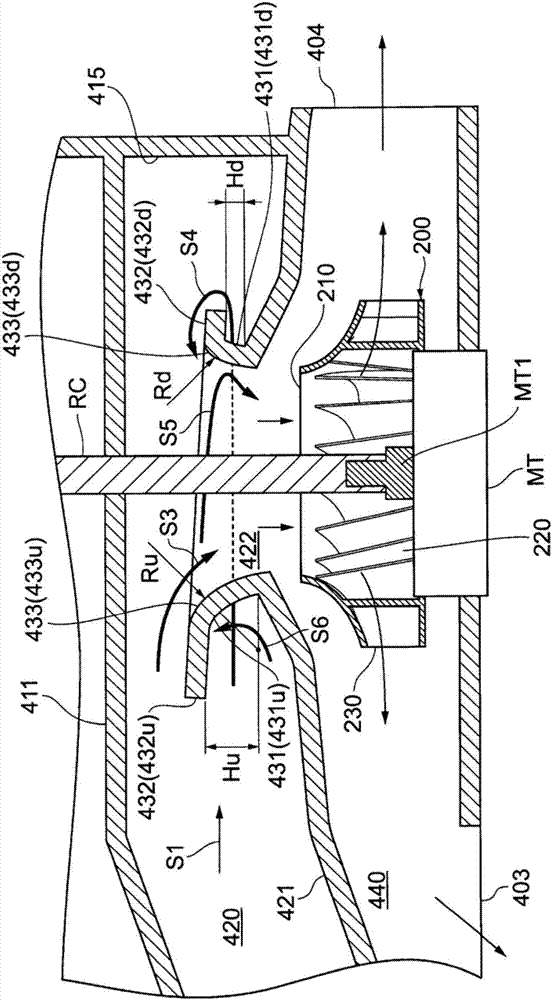
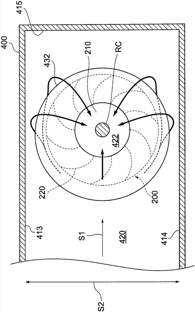
The purpose of the present invention is to provide a vehicular air-conditioning apparatus which has a compact configuration and allows noise and flow path resistance to be minimized. This vehicular air-conditioning apparatus is equipped with a centrifugal fan (200) and a casing (400). By rotating about a rotary shaft (RC), the centrifugal fan sucks in air along the rotary shaft through a fan suction opening (210) and radially blows out the air. The casing has a fan housing chamber (440), an introduction flow path (420), and a wall body (421). The fan housing chamber houses the centrifugal fan.The introduction flow path causes the air taken from the outside to flow in a first direction crossing the rotary shaft and introduces the air into the centrifugal fan. The wall body separates the fan housing chamber and the introduction flow path, and is formed with an opening (422) in a site facing the fan suction opening. The peripheral edge of the opening is provided with an annular protrusion (431) that protrudes toward the introduction flow path from the wall body and covers the opening.

Description

[0001] Cross-reference of related applications [0002] This application is based on the JP Patent application 2015-091133 for which it applied on April 28, 2015, The content of an indication is incorporated in this application as a reference. technical field [0003] The invention relates to a vehicle air conditioner. Background technique [0004] A known vehicle air conditioner includes: a centrifugal fan that sucks air in a direction along a rotation axis; and a case that accommodates the centrifugal fan. A flow path is formed inside the casing, and when the centrifugal fan rotates, air is drawn into the flow path from the interior and exterior of the vehicle by the negative pressure associated with the rotation. [0005] The flow path inside the casing is equipped with temperature adjustment equipment such as an evaporator and a heater core. The air taken in the flow path is blown out into the vehicle interior after being appropriately temperature-regulated by these te...

Claims


Application Information

Patent Timeline
Patent Type & Authority Applications(China)
IPC IPC(8): B60H1/00F24F1/00F24F13/30
CPCB60H1/00471B60H1/00064B60H2001/00135B60H1/00849B60H2001/00099B60H2001/006
Inventor 小田修三今东升一
Owner DENSO CORP
Learn More